SC 32 / SC 64
215
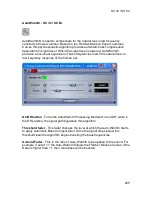
PeakStopPlus® On/Off
- The first stage of PeakStopPlus is the Instantaneous
Transient Clamp™ which clamps the signal with a soft logarithmic clamp
function. This logarithmic function ensures that the signal will not exceed the
level set by the PeakStopPlus Overshoot control by more than the Overshoot
amount, and that it will not introduce harsh artifacts. The second stage is a
unique program limiter featuring Intelligent Predictive Limiting™. Its function is to
monitor the input signal and intelligently predict the amount of gain reduction
needed to keep the output signal below the ceiling set by the Instantaneous
Transient Clamp™.
Overshoot 2 dB - 6 dB
- This parameter sets the amount of overshoot for the
Instantaneous Transient Clamp™.
Auto Button On/Off
- When Auto mode is on, this insert dynamically sets the
Attack, Hold, and Release times for the signal. The Auto mode constantly adjusts
these parameters in real time for optimum performance from the Limiter. You will
find that for most applications, not only is using the Auto mode faster and easier
but by letting the Limiter constantly tweak these parameters, the outcome will
sound better.
Attack Fader
- Attack is how fast the Limiter starts to reduce the gain after the
signal crosses the Threshold. Fast Attack is useful when dealing with very fast
transients. The Attack control is not active when in Auto mode.
Hold Fader
- Hold is the amount of time the limiter remains in gain reduction
after the signal has dropped below the threshold. A longer hold time is useful in
smoothing out the sound when limiting several fast peaks that are fairly close
together in time. The hold control is not active while in auto mode.
Release Fader
- Release is how fast the signal comes out of compression. The
release is in dB per second. For example, if release is set to 5 dB /sec, and the
signal is at 10dB of gain reduction, the Release time is 2 seconds. Having a
Release time that is either too fast or too slow for the signal can result in audible
artifacts called 'pumping' or 'breathing'. This can cause volume drops in your
signal that may not be desired. The Release control is not active while in Auto
mode.
Содержание SC 32
Страница 1: ...SC32 SC64 Help ...
Страница 2: ......
Страница 5: ...1 SC 32 SC 64 SC 32 SC 64 Overview Philosophy ...
Страница 8: ...SC32 SC64 Help 4 ...
Страница 10: ...SC32 SC64 Help 6 ...
Страница 25: ...SC 32 SC 64 21 Power Input SC 32 SC 64 Power Connector IEC power connector ...
Страница 37: ...SC 32 SC 64 33 Edit Menu SC 32 SC 64 The Edit menu allows copy and paste functions ...
Страница 39: ...SC 32 SC 64 35 This can be helpful when switching from editor to editor during programming ...
Страница 61: ...SC 32 SC 64 57 One Group Added ...
Страница 62: ...SC32 SC64 Help 58 Channels one Channel 1 and ten Channel 10 moved to the new group ...
Страница 63: ...SC 32 SC 64 59 ...
Страница 75: ...SC 32 SC 64 71 Channel 65 and Channel 70 moved to the new group ...
Страница 76: ...SC32 SC64 Help 72 ...
Страница 84: ...SC32 SC64 Help 80 ZC 2 ZC 3 ZC 4 ZC Fire ZC 6 ZC 7 ZC 8 ZC 9 ...
Страница 94: ...SC32 SC64 Help 90 ...
Страница 149: ...SC 32 SC 64 145 Click on OK and your action is set Complete the preceding steps for actions in the remaining positions ...
Страница 169: ...SC 32 SC 64 165 Each tab of the I O Card Meters window will show the 8 meters associated with that Input or Output card ...
Страница 174: ...SC32 SC64 Help 170 ...
Страница 176: ...SC32 SC64 Help 172 Input Gate GATE Input Inserts INS1 INS2 ...
Страница 178: ...SC32 SC64 Help 174 Click on the Names and Routes link under Inputs to configure Routes and Channel Labels ...
Страница 185: ...SC 32 SC 64 181 ...
Страница 193: ...SC 32 SC 64 189 ...
Страница 201: ...SC 32 SC 64 197 Output Bandpass Filter Crossover BPF Output EQ PEQ Output Limiter LIM Output Delay DLY ...
Страница 205: ...SC 32 SC 64 201 or select the Output DSP Inserts link ...
Страница 206: ...SC32 SC64 Help 202 ...
Страница 230: ...SC32 SC64 Help 226 ...

