background image

5

2.5 FALL 

CLEARANCE:

 Ensure suf

fi

 cient clearance exists in your fall path to prevent striking an object during 

a fall. The clearance required is dependent upon the subsystem (rope grab and lanyard, rope grab and 

carabiner) and lifeline properties. Table 1 shows the approximate elongation for new DBI/SALA lifelines in 

dry conditions. The elongation speci

fi

 ed is for an applied static load of 1,800 lbs (8 kN). Lifeline elongation 

must be considered when estimating fall clearance. Factors that affect fall clearance include:

•  

Elevation of anchorage

• 

Free fall distance

• 

 Worker height

• 

Connecting subsystem length

• 

Lifeline elongation. See Table 1:

•  

Deceleration distance

• 

 Movement of harness attachment element

Table 1 - Life Line Elongation: ft (m)

Lifeline Type

Lifeline Lenght: ft (m)

25 (8) - 75 (23)

100 (30)

150 (46)

3/8” Wire Rope

0.43 (0.13)

0.65 (0.2)

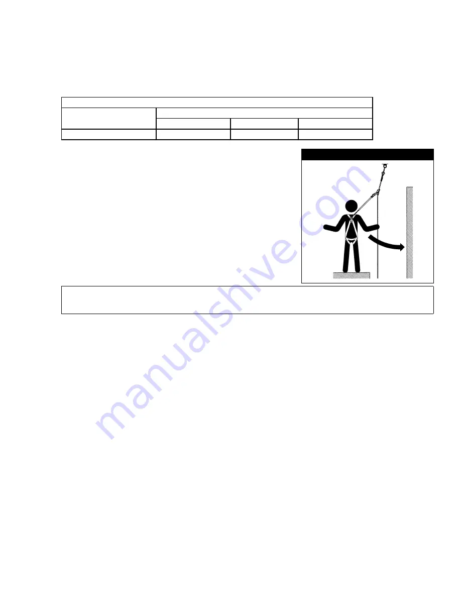
2.6 SWING 

FALLS:

 Swing Falls occur when the anchorage point is 

not directly above the point where a fall occurs (see Figure 4). 

The force of striking an object in a swing fall may cause serious 

injury or death. Minimize swing falls by working as close to the 

anchorage point as possible. Do not permit a swing fall if injury 

could occur. Swing falls will signi

fi

 cantly increase the clearance 

required when a SRL (self-retracting lifeline) or other variable 

length connecting subsystem is used.

2.7 ENVIRONMENTAL 

HAZARDS:

 Use of this equipment in areas 

with environmental hazards may require additional precautions 

to prevent injury to the user or damage to the equipment. 

Hazards may include, but are not limited to; heat, chemicals, 

corrosive environments, high voltage power lines, gases, moving 

machinery, and sharp edges.

Figure 4  –   Swing Falls

Swing Fall Hazard

WARNING:

 When working with tools, materials, or in high temperature environments, ensure that 

associated fall protection equipment can withstand high temperatures, or provide protection for those 

items.

2.8  COMPATIBILITY OF COMPONENTS:

 Capital Safety equipment is designed for use with Capital Safety 

approved components and subsystems only. Substitutions or replacements made with non-approved 

components or subsystems may jeopardize compatibility of equipment and may effect the safety and 

reliability of the complete system. 

2.9  COMPATIBILITY OF CONNECTORS:

 Connectors are considered to be compatible with connecting 

elements when they have been designed to work together in such a way that their sizes and shapes do not 

cause their gate mechanisms to inadvertently open regardless of how they become oriented. Contact Capital 

Safety if you have any questions about compatibility.


Connectors (hooks, carabiners, and D-rings) must be capable of supporting at least 5,000 lbs (22.2 kN). 

Connectors must be compatible with the anchorage or other system components. Do not use equipment 

that is not compatible. Non-compatible connectors may unintentionally disengage (see Figure 5). Connectors 

must be compatible in size, shape, and strength. If the connecting element to which a snap hook (shown) or 

carabiner attaches is undersized or irregular in shape, a situation could occur where the connecting element 

applies a force to the gate of the snap hook or carabiner. This force may cause the gate (of either a self-

locking or a non-locking snap hook) to open, allowing the snap hook or carabiner to disengage from the 

connecting point. Self- locking snap hooks and carabiners are required.

Содержание LAD-SAF 5000338

Страница 1: ... MANUAL Figure 1 Static Wire Rope Grab Model Description Cable Requirements 5000338 Wire Rope Grab For use with 9 5 mm 3 8 in diameter 7x19 Galvanized or Stainless Steel Cable FORM NO 5906265 REV E LAD SAF STATIC WIRE ROPE GRAB FOR 3 8 INCH WIRE CABLE Model Number 5000338 ...

Страница 2: ...2 ...

Страница 3: ...bility of this equipment for your application contact Capital Safety IMPORTANT Before using this equipment record the product identification information from the ID label in the Inspection and Maintenance Log at the back of this manual DESCRIPTION This Wire Rope Grab is intended to be used as part of a personal fall arrest system or restraint system The wire rope grab provides a portable lanyard c...

Страница 4: ...he user before each use by following the procedures defined in Table 2 Inspection Checklist and additionally by a competent person1 other than the user at intervals of no more than one year2 Results of each Competent Person inspection should be recorded in the Inspection and Maintenance Log in the back of this manual 2 0 LIMITATIONS REQUIREMENTS Always consider the following limitations and requir...

Страница 5: ...ts high voltage power lines gases moving machinery and sharp edges Figure 4 Swing Falls Swing Fall Hazard WARNING When working with tools materials or in high temperature environments ensure that associated fall protection equipment can withstand high temperatures or provide protection for those items 2 8 COMPATIBILITY OF COMPONENTS Capital Safety equipment is designed for use with Capital Safety ...

Страница 6: ... close and lock or that roll out could occur G In a manner that does not allow the connector to align properly while under load 2 11 CONNECTING SUBSYSTEMS Connecting subsystems self retracting lifeline lanyard rope grab and lifeline cable sleeve etc must be suitable for your application See section 1 1 See the subsystem manufacturer s instructions for additional information Some SRL models have we...

Страница 7: ...d or grain 3 5 CONNECTING THE DETACHABLE WIRE ROPE GRAB TO THE LIFELINE WARNING In situations where a fall hazard exists use a back up fall arrest system such as a lanyard to protect against a fall Step 1 Figure 7 Hold the wire rope grab in the up position as indicated by an arrow stamped on the wire rope grab body Step 2 Figure 8 Open the wire rope grab by pressing the button on both detent pins ...

Страница 8: ...releasing The wire rope grab must lock onto the lifeline Do not use if the wire rope grab will not operate correctly 4 0 TRAINING 4 1 It is the responsibility of all users of this equipment to understand these instructions and to be trained in the correct installation use and maintenance of this equipment These individuals must be aware of the consequences of improper installation or use of this e...

Страница 9: ...the lifeline F according to the manufacturer s instructions Lanyard Inspect the Lanyard per the manufacturer s instructions Full Body Harness Inspect the Full Body Harness per the manufacturer s instructions 6 0 CLEANING MAINTENANCE AND STORAGE 6 1 Periodically clean the Lad Saf Wire Rope Grab using water and mild detergent Clean the label as required 6 2 Replacement parts and additional maintenan...

Страница 10: ...10 8 0 LABELING This Identification Label must be present and completely legible ...

Страница 11: ...NSPECTION DATE INSPECTION ITEMS NOTED CORRECTIVE ACTION MAINTENANCE PERFORMED Approved By Approved By Approved By Approved By Approved By Approved By Approved By Approved By Approved By Approved By Approved By Approved By Approved By Approved By Approved By Approved By Approved By Approved By ...

Страница 12: ... ANY IMPLIED WARRANTIES OF MERCHANTABILITY OR FITNESS FOR A PARTICULAR PURPOSE AND SHALL NOT BE LIABLE FOR INCIDENTAL PUNITIVE OR CONSEQUENTIAL DAMAGES OF ANY NATURE INCLUDING WITHOUT LIMITATION LOST PROFITS REVENUES OR PRODUCTIVITY OR FOR BODILY INJURY OR DEATH OR LOSS OR DAMAGE TO PROPERTY UNDER ANY THEORY OF LIABILITY INCLUDING WITHOUT LIMITATION CONTRACT WARRANTY STRICT LIABILITY TORT INCLUDIN...

Отзывы: