background image

3: Operation

RT7000-MSOP

3-5

Alpha

Pressing 

ALPHA

 allows access to the Alpha menu. To exit the menu, press 

ALPHA

 again. For information on this menu, 

refer to "Alpha Menu 

Described" on page 3-8.

Scan Group

A scan group is a collection of channels grouped together. Turn the 

FUNCTION

 knob until the 

SCAN GROUP

 icon flashes. Press 

STATUS

 to 

select a scan group. For more information on selecting scan groups, 

refer to 

"Selecting a Scan Group" on page 3-19.

RF Power Level

Turn the 

FUNCTION

 knob until the 

RF PWR

 icon flashes. Press 

STATUS


to scroll through the 

L

 (low), 

M

 (medium), and 

H

 (high) power settings. 

Default settings for the three RF power levels are as follows:

To change these values, 

refer to "Using Menus to Change Settings" on page 3-

6.


RX Attenuator

Turn the 

FUNCTION

 knob until the 

ATTN

 icon flashes. Press 

STATUS

 to 

change the status of the input receiver attenuator from 

ON

 (+20 dB input RX 

pad) to 

OFF

 or vice versa.

External RF 
Amplifier

Turn the 

FUNCTION

 knob until the 

EXT AMP

 icon flashes. Press 

STATUS


to provide PTT control from accessory


3 of the RT7000 to an external 

amplifier. To automatically set and lock RF power in the 

H

 (high power) 

position, set it to 

ON

. To restore control, set it to 

OFF 

and the RT7000 no 

longer requires an external amplifier.

Squelch

Turn the 

FUNCTION

 knob until the 

SQ

 icon flashes. Press 

STATUS

 to 

change the status of the transceiver squelch circuit from 

ON

 to 

OFF

 or vice 

versa. In the 

ON

 setting, background noise is muted.

RF Power Level

Factory Preset

ALPHA 5 Setting

L (Low)

10W (average power)

10

M (Medium)

25W (average power)

30

H (High)

100W (average power)

200

Содержание RT7000

Страница 1: ...nsceiver Operator Manual Datron World Communications Inc Manual Part No RT7000 MSOP Release Date June 2007 Revision F 3030 Enterprise Court Vista CA 92081 U S A Phone 760 597 1500 Fax 760 597 1510 E Mail sales dtwc com www dtwc com ...

Страница 2: ......

Страница 3: ...MSOP i Change Description Date of Revision Revision Letter Description of Changes Pages Affected 6 2007 F Reformatted and updated with inclusion of addendum 966001 LQA Scoring and the FALC option 1 4 3 13 3 16 ...

Страница 4: ......

Страница 5: ...to demonstrate that a remedy has been implemented If the user fails to perform the agreement will be terminated by further written notice from Datron Upon termination the user shall immediately return all original Software documentation and any copies of each to Datron This Software is licensed AS IS and Datron provides a war ranty that covers the media upon which the Software is embed ded for a p...

Страница 6: ... of equipment 3 Date of installation Parts returned without this information will not be replaced In the event of a dispute over the age of the replacement part components date coded over 24 months previously will be considered out of warranty Remedies Buyer s sole remedies and the entire liability of Datron are set forth above In no event will Datron be liable to Buyer or any other person for any...

Страница 7: ...Connections 2 3 Figure 2 3 Power Cabling Accessories 2 6 Figure 2 4 RF Cabling Accessories 2 7 Figure 2 5 Control Cabling Accessories 2 8 Operations Check 2 9 Chapter 3 Operation Powering the RT7000 3 1 Figure 3 1 Front Panel Features 3 1 Using Knobs Buttons and Indicators 3 2 Using Menus to Change Settings 3 6 Table 3 1 Alpha Menu 3 6 Table 3 2 ALE Submenu 3 12 Customizing Channel and Frequency 3...

Страница 8: ...vi RT7000 MSOP Chapter 4 Servicing Routine Maintenance 4 1 Board Access and Replacement 4 1 Figure 4 1 Board Locations 4 2 Field Level Servicing 4 2 ...

Страница 9: ...ex and half duplex capability and a full alphanumeric keypad for frequency or text entry The RT7000 is packaged in a rugged waterproof housing designed to withstand harsh environments This manual describes the RT7000 including its installation operation and organizational maintenance features For complete technical information refer to the RT7000 HF Transceiver technical manual RT7000 MS Descripti...

Страница 10: ...fications Note Specifications are subject to change without notice or obligation Characteristic Specification General Frequency range 1 6 to 30 MHz TX 100 Hz to 30 MHz RX 10 Hz channel spacing Preset channels 256 standard 1000 optional Scanning Multiple scan groups operator selectable scan rates Channel programming From front panel or remotely via computer or dedicated remote control console Frequ...

Страница 11: ...The RT5830 requires the RT7000 to have both the RT7000PP and the RT5830INST The RT7000 is not field upgradeable to an RT7000PP RT7000RF Designed for long distance remote only use beyond 2 km A blank front panel replaces the standard front panel An internal modem card 7000RF is installed For full function FSK remote control use with the RT7201F Cooling Rear panel heatsink RT7000FAN 1 fan kit option...

Страница 12: ...plete 1045 capability including link quality analysis auto linking sounding and orderwire message transmission and reception 7000CLK Internal clock keeps and displays the time and includes alarm features 7000CW Narrowband filter with 500 Hz bandwidth for CW operation 7000ENCR High level voice encryptor uses enhanced domain transform EDT ciphering techniques providing long term security 7000FALC Fa...

Страница 13: ...roup delay characteristics for data operation RT7000AIRSELCALL Operating with N 1304A or equivalent SELCAL devices and Datron power amplifiers it adds a secondary control line to the radio and allows use of the ICAO mandated ground to air SELCAL 3 tone system Conventions Bold type is used to denote all items that appear in the display area and for any button knob or connector used on the front or ...

Страница 14: ......

Страница 15: ...nless otherwise specified when ordered the RT7000 is shipped ready for operation It is also available for mounting in a rack provided the appropriate rack kit is ordered Make sure the temperature at the location is within the specified range and that there is adequate ventilation around the rear of the RT7000 to allow for air flow The RT7000 has a rear panel heat sink to dissipate heat that is gen...

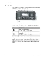
Страница 16: ...hm Most dynamic ceramic or magnetic microphones operate satisfactorily with the RT7000 All Datron supplied audio accessories have the correct mating connector on them To use other low level audio accessories obtain the correct mating connector from Datron Figure 2 1 Front Panel Connections Part Description MRR Heavy duty hand microphone MHS U S MIL STYLE H 189 U handset KYR Morse key HPR Headphone...

Страница 17: ...onal voltage range of the transceiver is 11 to 15 5 Vdc The RT7000 28 requires 28 Vdc at a maximum of 15A range of 22 30 Vdc The DC input connector on the rear panel is a 2 pin 30A circular receptacle that has a square mounting flange with 2 male pins The mating plug is attached to the input DC power cable C991556 This cable supplied with the RT7000 has a convenient connection to a variety of DC p...

Страница 18: ...r control cabling refer to the Control Cabling Accessories figure on page 2 8 For more information on any individual accessory refer to the manual for that piece of equipment There are three accessory connectors on the rear panel each with different pin assignments If multiple accessories are required that share one or more of the accessory connectors an external accessory combiner box RT7000IOX c...

Страница 19: ...000C connect to Accessory 2 The AT RAT7000 uses Accessory 3 Data Terminal Interface The RT7000 interfaces with its own line of data terminals or to other external units using Accessories 1 and 2 External Printers A standard parallel printer connects to Accessory 1 to obtain a hard copy of text messages stored in the RT7000 ALE Transcall Selcall Alarm The external ALE Transcall Selcall alarm driver...

Страница 20: ...60Hz Power Source 12 Vdc Power Source RT5850 12Vdc Power Source RT7000 12 28 DC INPUT FUSE REM ACC3 ACC2 ACC1 ANTENNA 110 220 50 60Hz Power Source C991511 UPF7000 12 28 C991556 DC Power Source 10 30 Vdc C992042 RT7201 RA400 RF OUTPUT RF INPUT J2 DC IN DC OUT J3 J4 J5 J6 ATU CONTROL IN ATU CONTROL OUT AMP CONTROL J1 J7 110 220 50 60Hz Power Source DC Power Source ACC1 REMOTE AC INPUT DC INPUT C9920...

Страница 21: ...ND RF IN RF OUT RA1000D IN OUT RF IN RF OUT RA400 F1 F2 GND C991510 RAT1000C RAT7000B C991505 C991505 C991526 C991620 C991559 RT7000 12 28 DC INPUT FUSE REM ACC3 ACC2 ACC1 ANTENNA RA400 RF OUTPUT RF INPUT J2 DC IN DC OUT J3 J4 J5 J6 ATU CONTROL IN ATU CONTROL OUT AMP CONTROL J1 J7 ...

Страница 22: ...RF IN RF OUT RA1000D RAT1000C RT7000 12 28 DC INPUT FUSE REM ACC3 ACC2 ACC1 ANTENNA RT7201 RT7201E IN OUT RF IN RF OUT RA400 F1 F2 GND RA400 RF OUTPUT RF INPUT J2 DC IN DC OUT J3 J4 J5 J6 ATU CONTROL IN ATU CONTROL OUT AMP CONTROL J1 J7 C992216 C991943 C992060 RAT1000P Amp Radio Access Tuner C991925 J7 Control C991933 Options Note Using the RAT1000P 28V radios can use cable C991933 to provide powe...

Страница 23: ...ontrolled remotely from longer distances using the RT7201F and the RT7201I remote control heads Both control heads require that you install modem interface boards 7000RF or 7000RI inside the RT7000 The RT7201F uses FSK and is for long range remote requirements while the RT7201I uses ISDN and is for real time control up to 2 km These modem based remote control units connect to the RT7000 via the re...

Страница 24: ......

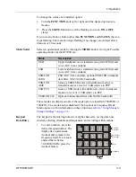
Страница 25: ...isplay RT7000 VER 701xx where xx is the version level The BITE system runs automatically and indicates that everything is functional Display RT7000 MODULES OK The BITE system searches for any installed options These options are displayed with the current channel number upper left corner channel frequency upper center and clarifier offset if any below the frequency Figure 3 1 Front Panel Features M...

Страница 26: ...n Clarifier Clarifier offset for the RT7000 is achieved by turning the CLAR knob counterclockwise for negative offset and clockwise for positive offset USB mode The knob has continuous rotation and provides a maximum of 600 Hz and 600 Hz offset in 10 Hz steps This offset is shown beneath the frequency It can be nulled manually by turning the knob until the offset reads 000 Hz Note You can also tog...

Страница 27: ...a once entered selecting channels and frequencies and scrolling within menus To enter numbers press the desired keypad number The display has a permanent decimal and comma in the frequency field If a value is entered that is below 10 000000 MHz press the decimal button Mode Description USB Upper sideband voice standard voice grade IF filter and voice AGC time constants LSB Lower sideband voice sta...

Страница 28: ...de The scrolling rate remains constant for the duration of time an arrow button is held down The arrows remain active until another control function is used To select a channel press C To select a frequency press F To save entered data press E Tune If the AT RAT7000B or RAT1000C antenna tuner is connected to the RT7000 pressing the TUNE button activates the tune cycle Call Send Turn the FUNCTION k...

Страница 29: ...Menus to Change Settings on page 3 6 RX Attenuator Turn the FUNCTION knob until the ATTN icon flashes Press STATUS to change the status of the input receiver attenuator from ON 20 dB input RX pad to OFF or vice versa External RF Amplifier Turn the FUNCTION knob until the EXT AMP icon flashes Press STATUS to provide PTT control from accessory 3 of the RT7000 to an external amplifier To automaticall...

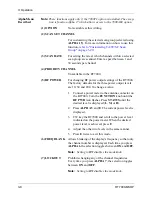
Страница 30: ...nd press E 3 Once you select and enter a function use the arrow buttons to scroll through further selections within that function Press E to enter or access a selection For example press ALPHA 17 and E to access the ALE submenu Alpha Menu Table 3 1 Alpha Menu Alpha Function Description 1 OPTION not used 2 SCAN SET CHANNEL for non ALE 3 SCAN RATE for non ALE 4 PRIORITY CHANNEL 5 RF POWER TX 6 FREQ ...

Страница 31: ...1 TYPE Voice Enhancement Modulation 22 COM 1 BAUD comport 1 configuration 23 COM 2 BAUD comport 2 configuration 24 BACKLITE OUT ON OFF 25 FREQ INC HZ frequency increment from 1 Hz to 10 MHz 26 TEST REAR PANEL I O factory test 27 ENC PASSWORD Encryption menu 28 PTT TIMER sets maximum PTT time 29 PRINTER 30 CLONE RADIO 31 GLOBAL POSITION SYSTEM optional 32 CW HOLD TIME 33 SPLIT SITE 2 radios TX and ...

Страница 32: ... the three power output levels are 10 30 and 200 To change a value 1 Connect a power meter to the antenna connector on the RT7000 Turn the FUNCTION knob until the RF PWR icon flashes Press STATUS until the desired level is displayed L M or H 2 Press ALPHA 5 and E The current power level is displayed 3 CW key the RT7000 and scroll to the power level indicated on the power meter When the desired pow...

Страница 33: ...he sounding of the internal alarm Enter the year date hour and minute pressing E after each value 12 TIME AND DATE Automatically displays the setting of the internal clock 13 TA TS SC Rx ADDR For selection of a self ID The current self ID is briefly displayed Use numbers from 000 to 255 This number is usually the last three digits of a serial number 14 TRANSADAPT BER NUM For setting the bit error ...

Страница 34: ...el from 0 to 33 20 BITE TEST INITIATED Automatically starts the RT7000 BITE system 21 OPTION 1 TYPE Allows activation of the Voice Enhancement option if the 7000VEM is installed in the option card slot For more information refer to Activating Voice Enhance ment on page 3 25 22 COM 1 BAUD For configuring the RT7000 COM1 port if you are working from a computer Use the arrow buttons to scroll through...

Страница 35: ...00 if an external printer is connected 30 CLONE RADIO Allows cloning of another transceiver by downloading all frequency and channel settings 31 GLOBAL POSITION SYSTEM For configuring an external GPS device 32 CW HOLD TIME For setting the continuous wave hold time Enter the number in msec 33 SPLIT SITE For configuring two radios receive only master and transmit only slave The receive radio control...

Страница 36: ...SND ADRS sound address 12 SND LEN sound length 13 SND INT sound interval 14 CALL LIM call limit 15 SLF TMOUT self time out 16 OTR TMOUT other time out 17 AUTO FILL 18 LQA EXCNG Link Quality Analysis exchange 19 LQA DECAY Link Quality Analysis decay 20 BER THRSD Bit Error Rate threshold 21 GOLAY THD Golay threshold 22 ERR THRSD error threshold 23 MESSG OUT message out 24 NEW MESSG new message 25 ME...

Страница 37: ...ting an ALE scan group from 0 to 9 This becomes the specified scan group when using 3 TUNE GRP and 9 MOD GRP 3 TUNE GRP For automatically tuning an ALE scan group from 0 to 9 This tunes all the channels in that scan group 4 Rx SELCT For selecting a receive type 1 for normal ALE receive transmit Rx Tx 2 for receive only Rx ONLY or 3 for channel setup CH Rx Tx of the RC2 software 5 SELF ADRS For sel...

Страница 38: ...ng Enter 1 for sound OFF and 2 for sound ON 11 SND ADRS For setting the sounding feature to the self address selected in 5 SELF ADRS 12 SND LEN For setting the length of each sounding transmission The recommended sounding length is 5 or 10 seconds 13 SND INT For setting the time intervals for sounding Enter from 1 minute to 24 hours 0001 to 1439 minutes 14 CALL LIM For limiting the number of attem...

Страница 39: ...tions while a value of 4 is the maximum amount of corrections allowable The factory default is set to 3 allowable errors 22 ERR THRSD For controlling the number of errors allowed before a word is rejected 0 4 A value of 0 allows for no errors while a value of 4 is the maximum amount of errors allowable The factory default is set to 3 allowable errors 23 MESSG OUT For assigning a number to an outgo...

Страница 40: ...work 31 SET TO For selecting a Other station address to determine it s LQA score for each of its channels This applies to radios with software version 701BD or later Use the up and down arrow buttons on the keypad to scroll through the Other Addresses until the desired other station is found Or enter the number using the keypad Press E to enter the selection the Other ID and Other Address line goe...

Страница 41: ...1 6 MHz to 30 000000 MHz in transmit mode Simplex operation uses identical RX and TX frequencies and must be in the transmit mode range Enter semi duplex split frequency as an RX frequency first and then as a TX frequency If you enter a frequency that is out of range an error message is displayed and the previous frequency is restored When you enter a frequency always include the decimal point unl...

Страница 42: ...uency is displayed 6 Press F to toggle between the receive and transmit frequencies Example To enter an RX frequency of 21 2 MHz and a TX frequency of 29 3 MHz on channel 41 1 Press C and 41 and E Display CH FREQ 041 xx xxx xxx where xx xxx xxx is the existing channel frequency 2 Press F and 21 2 Display 041 21 200000 Rx 3 Press F and 29 3 and E Display 041 29 300000 Tx Note If you enter any numbe...

Страница 43: ... for TA TC only Scan groups are arranged in the RT7000 according to number You can have up to 32 different scan groups in the transceiver at one time each one having a different scan group number Each scan group can have up to 64 channels Because the RT7000 scans channels not frequencies you must give all desired frequencies in a particular scan group a channel number Channel numbers are not exclu...

Страница 44: ... to locate the channel to delete 2 Using the alpha characters on the keypad press D delete 3 Press E To add new channels to the group 1 Use the up arrow to scroll past the highest numbered channel until xxx is displayed 2 Enter the number of the channel to add and press E 3 Continue adding channels as necessary Press E to exit this mode You can delete and enter a different single digit channel by ...

Страница 45: ... the link RE LINK Automatically chooses the best possible channel using the information from a prior THIS IS call POLLING Automatically completes a THIS WAS call on each of the scan group channels Link quality information is recorded for each channel 5 Press CALL SEND to make the selection 6 Scroll to the type of call you are making INDIVIDUAL or NET Press CALL SEND to make the selection Display T...

Страница 46: ...etermines the best channel in a scan group for communications TransAdapt is a faster system that determines if the selected channel is acceptable for voice quality communications not necessarily the best Call Setup Before you initiate a call turn on the appropriate option as follows 1 Turn the FUNCTION knob until the correct icon flashes TCSC or TA 2 Press STATUS to turn the option ON You can only...

Страница 47: ...AN 4 Press CALL SEND to initiate the call 5 Enter the Transcall code of the transceiver to call 001 255 A call to all channels Allcall is code 000 6 Press CALL SEND again The RT7000 is now under full control of the Transcall circuit The RT7000 starts transmission on each of the ten channels until it is synchronized with the station to call When synchronized both transceivers step through each chan...

Страница 48: ...annels until it is synchronized with the station called Display TA LINK If the call is unsuccessful calling discontinues and NO LINK is briefly displayed 7 To break the connection press SCAN 8 To stop the call before connecting press CALL SEND Activating the Noise Blanker The Noise Blanker option 7000NB eliminates impulse type interference in high noise environments 1 Turn the FUNCTION knob until ...

Страница 49: ...es atmospheric noise and static normal with HF signals Mode 2 adds the ability to remove man made interferences like ignition and power line noises 1 Turn the FUNCTION knob until the OPT icon flashes 2 Press STATUS to turn the option ON 3 Press ALPHA 21 and E Display OPTION 1 TYPE x briefly displays last mode entered 4 Enter the mode 1 or 2 and press E Note To verify that the 7000VEM option is ins...

Страница 50: ......

Страница 51: ...k the calibration of the master oscillator It is often convenient to program an unused channel to a known frequency standard such as WWV radiates 10 000W on 5 10 and 15 MHz This enables regular checks of the frequency calibration Keep the exterior of the RT7000 clean by wiping it with a damp cloth and polishing it with a soft dry cloth Make sure all knobs are secure and connectors tight If you ope...

Страница 52: ... refer to the RT7000 technical manual RT7000 MS Figure 4 1 Board Locations Processor Front Panel Processor Display Keypad RF Amplifier RF Filter DC DC Convertor 28V only Interface Power Supply Motherboard ALE FSK ISDN OPT2 OPT1 Audio 75 MHz 5 MHz Synthesizer Noise Blanker Reference Control Part Number Description 004 01110 Front panel processor 001 00206 Reference control board 004 12260 004 28260...

Страница 53: ...e RT7000 001 01101 Processor board 001 01300 ALE board 001 01200 Squelch board 004 28100 DC DC converter 28V Part Number Description RT7000TK Tool kit with card puller SMTRK Surface mount technology tool kit 7000EXT Extender board kit and card puller RT7000 MS Technical manual Part Number Description ...

Страница 54: ......

Отзывы: