INSTALLATION
27
2
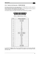
2.6.4 Camera Link Connector – VIDEO1/VIDEO2
The image acquired by the camera is provided on the CAMERA LINK connectors present on
the rear panel of the Camera Link DV9500 models.
The two connectors share exactly the same video and control signals and can be used to
connect the camera to two independent acquisition systems.
The serial port output is also shared, while the input is connected only to VIDEO1.
26
13
14
1
Figure 24 - CAMERA LINK 26-pin Connector
Pin
Channel Link Signal
1 Inner
shield
14 Inner
shield
2 X0-
15 X0+
3 X1-
16 X1+
4 X2-
17 X2+
5 Xclk-
18 Xclk+
6 X3-
19 X3+
7
SerTC+ (only VIDEO1)
20
SerTC- (only VIDEO1)
8 SerTFG-
21
9 CC1-
22 CC1+
10 CC2+
23 CC2-
11 CC3-
24 CC3+
12 CC4+
25 CC4-
13 Inner
shield
26 Inner
shield
To connect the CAMERA LINK signals to the DD9500 Decoder use Camera-Link cable CAB-
9305 (5 mt.) or CAB-9010 (10 mt.). Alternatively, it is possible to use a Standard Camera-
Link video cable.
Содержание DV9500 Series
Страница 1: ...DV9500 Installation Manual ...
Страница 2: ......
Страница 3: ...DV9500 Series Installation Manual ...

