PCM-3362 User Manual
62
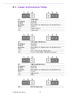
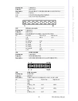
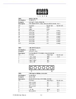
CN18
LAN Connector
Part Number
1653003719
Footprint
HD_5x2P_79_RA_21N22050
Description
PIN HEADER 5*2P 2.00mm 90D(M) SMD 21N22050-10J10
Pin
Pin Name
Signal Type
Signal Level
A1
GNDT
GND
A2
GNDT
GND
A3
I/O
Analog
A4
LAN1_M3-
I/O
Analog
A5
I/O
Analog
A6
I/O
Analog
A7
I/O
Analog
A8
I/O
Analog
A9
I/O
Analog
A10
I/O
Analog
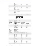
CN19
LAN LED Connector
Part Number
1653004101
Footprint
HD_4x1P_79_D
Description
PIN HEADER 4*1P 180D(M) 2.0mm DIP WO/Pb
Pin
Pin Name
Signal Type
Signal Level
1
+V3.3_LAN1
PWR
+3.3V
2
LAN1_ACT#
OUT
3 LAN1_1000#
OUT
4 LAN1_100#
OUT
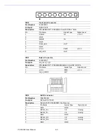
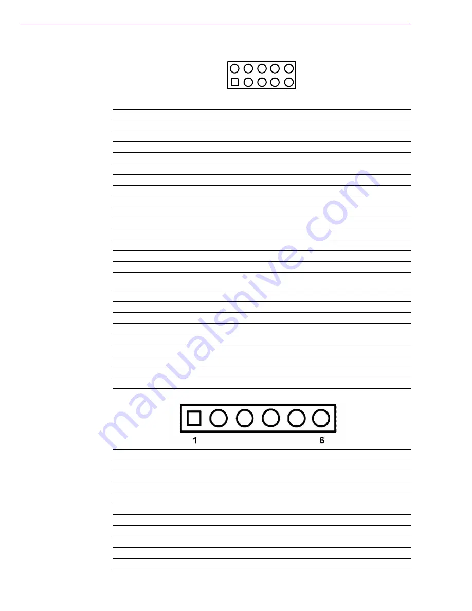
CN20
PS2 Keyboard/Mouse Connector
Part Number
1655306020
Footprint
WHL6V-2M
Description
WAFER BOX 2.0mm 6P 180D(M) W/LOCK
Pin
Pin Name
Signal Type
Signal Level
1
KB_z_CLK#
I/O
+5 V
2
KB_z_DAT#
I/O
+5 V
3
MS_z_CLK#
I/O
+5 V
4
GND
5
+V5_KB
PWR
+5 V
6
MS_z_DAT#
I/O
+5 V
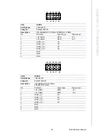
3
6
4
5
2
8
9
7
10
1
Содержание PCM-3362
Страница 1: ...Data Modul AG www data modul com Specification PCM 3362 ...
Страница 12: ...5 PCM 3362 User Manual Chapter 1 General Information Figure 1 2 Board layout Dimensions Solder Side ...
Страница 13: ...PCM 3362 User Manual 6 ...
Страница 14: ...Chapter 2 2 Hardware Installation ...
Страница 23: ...PCM 3362 User Manual 16 ...
Страница 24: ...Chapter 3 3 AMI BIOS Setup ...
Страница 44: ...Chapter 4 4 Software Introduction Installation ...
Страница 55: ...PCM 3362 User Manual 48 ...
Страница 56: ...Chapter 5 5 Chipset Software Installation Utility ...
Страница 58: ...Chapter 6 6 Integrated Graphic Device Setup ...
Страница 60: ...Chapter 7 7 LAN Configuration ...
Страница 75: ...PCM 3362 User Manual 68 ...
Страница 76: ...Appendix C C Mechanical Drawings ...
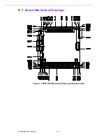
Страница 77: ...PCM 3362 User Manual 70 C 1 Board Mechanical Drawings Figure C 1 PCM 3362 Mechanical Drawing Component Side ...
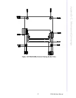
Страница 78: ...71 PCM 3362 User Manual Appendix C Mechanical Drawings Figure C 2 PCM 3362 Mechanical Drawing Solder Side ...
Страница 81: ...PCM 3362 User Manual 74 ...
Страница 82: ...Appendix D D Watchdog Timer and GPIO sample code ...


