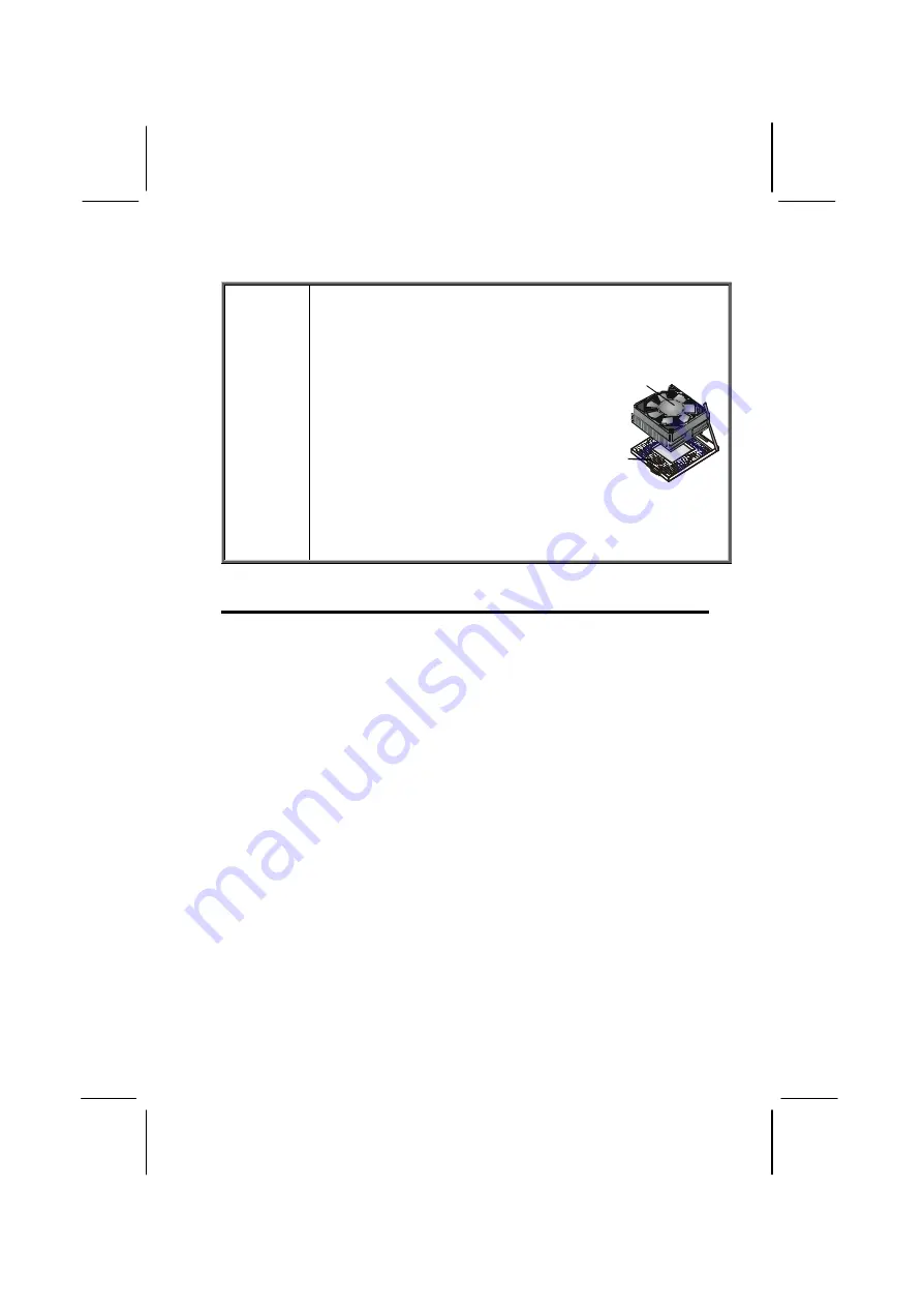
background image


Caution! 

When installing a CPU heatsink and 
cooling fan  make sure that  you DO NOT 
scratch the motherboard or any of  the 
surface-mount resistors with the clip of 
the cooling fan. If the clip of the cooling 
fan scrapes across the mainboard, you 
may cause serious damage to both the 
mainboard and the processor. 
On most mainboards, there are small 
surface-mount resistors near the proces-
sor socket, which may be damaged if the 
cooling fan is carelessly installed. 
Avoid using cooling fans with sharp 
edges on the fan casing and the clips. 
Also, install the cooling fan in a well-lit 
work area so that you can clearly see the 
mainboard and processor socket. 

Cooling fan and
heat sink

CPU socket

Important Information 

Copyright 

This publication, including all photographs, illustrations and 
software, is protected under international copyright laws, with all 
rights reserved. Neither this manual, nor any of the material con-
tained herein, may be reproduced without the express written 
consent of the manufacturer. 

Version 1.0  

Disclaimer 

The information in this document is subject to change without 
notice. The manufacturer makes no representations or warran-
ties with respect to the contents hereof and specifically disclaims 
any implied warranties of merchantability or fitness for any par-
ticular purpose. Further, the manufacturer reserves the right to 
revise this publication and to make changes from time to time in 
the content hereof without obligation of the manufacturer to no-
tify any person of such revision or changes. 

Summary of Contents for P6VXM2

Page 1: ...ng fan and heat sink CPU socket Important Information Copyright This publication including all photographs illustrations and software is protected under international copyright laws with all rights reserved Neither this manual nor any of the material con tained herein may be reproduced without the express written consent of the manufacturer Version 1 0 Disclaimer The information in this document i...

Page 2: ... radio communica tions However there is no guarantee that interference will not occur in a particular installation If this equipment does cause harmful interference to radio or television reception which can be determined by turning the equipment off and on the user is en couraged to try to correct the interference by one or more of the following measures q Reorient or relocate the receiving anten...

Page 3: ...d q This device must accept any interference received in cluding interference that may cause undesired operation Canadian Department of Communications This class B digital apparatus meets all requirements of the Ca nadian Interference causing Equipment Regulations Cet appareil numérique de la classe B respecte toutes les exi gences du Réglement sur le matériel brouilieur du Canada ...

Page 4: ...t of items that are shipped with the package Installation Use the Installation Chapter to learn how to install the main board and get your system up and running Setup Use the Setup Chapter to configure the mainboard for optimum performance Software Use the Software Chapter to learn how to install the software drivers and support programs that are provided with this main board ...

Page 5: ...INSTALLATION 7 Quick Installation Table 7 Before You Begin 8 Static Electricity 8 Choosing a Case 9 Preparing the Mainboard 10 Mainboard Guide 10 I O Ports Side View 12 How to Set Jumpers 13 Check the Jumper Settings 14 Installing the Mainboard in a Case 18 Connecting Internal Components 19 Installing Other Hardware 21 Installing the Processor 21 Install the Memory Modules 23 Installing a Hard Dis...

Page 6: ...nagement Setup Option 55 PNP PCI Configuration Option 61 PCI Health Status Option 63 Frequency Control Option 64 Load Fail Safe Defaults Option 65 Load OptimizedDefaults Option 65 Set Supervisor and User Passwords Options 66 Save Exit Setup Option 67 Exit Without Saving Option 67 CHAPTER 4 SOFTWARE 69 Auto installing under Windows 98 70 Folders for this Mainboard 73 Utility Folder Installation Not...

Page 7: ...I AT Attachment Packet Interface devices The PCI IDE also supports PIO Mode 3 and 4 UDMA33 66 IDE UDMA100 is optional and an ATAPI CD ROM Note The P6VXM2 supports two VIA South Bridge chipsets the VIA VT82C686A and the VIA VT82C686B The VIA VT82C686A is standard and supports UDMA33 66 The VIA VT82C686B is op tional and supports UDMA100 The mainboard accommodates PC 100 133 SDRAM Synchro nous DRAM ...

Page 8: ...product q Features highlights the functions and components that make this one of the best value mainboards on the mar ket Checklist Compare the contents of your mainboard package with the standard checklist below If any item is missing or appears dam aged please contact the vendor of your mainboard package Standard Items q One mainboard q One diskette drive ribbon cable and bracket q One IDE drive...

Page 9: ...r rated speed Warning Overclocking components can adversely affect the reliabil ity of the system and introduce errors into your system Overclocking can permanently damage the mainboard by generating excess heat in components that are run beyond the rated limits Components on this mainboard can be damaged by discharges of static electricity Handle the board carefully holding it by the edges Don t ...

Page 10: ...ddressing The integrated DRAM controller supports up to four double sided DIMMs consisting of EDO SDRAM or VCM SDRAM The NB chipset provides SDRAM with a 64 bit data interface The AGP interface is AGP specification Rev 2 0 compliant and supports 2x 4x 4x 3 3 1 5V devices The PCI bus interface com plies with PCI Rev 2 1 and supports 3 3V and power supplies Five PCI bus masters are supported in addi...

Page 11: ...rs at 12 or 1 5 Mbits sec The integrated super IO controller supports two serial ports an IR port parallel port and floppy disk controller functions There is also system monitor support providing system feedback of voltage temperature and fan speed conditions Inexpensive Memory The board has two DIMM sockets for the installation of 168 pin 3 3V non buffered DIMM memory modules The DIMM memory modu...

Page 12: ...late on the backplane includes two PS 2 ports for mouse and keyboard one serial port one VGA port one parallel port one MIDI game port two USB ports with an onboard header providing two extra USB ports and audio jacks for mi crophone line in and line out The board includes two PCI IDE channels and a floppy disk drive interface Programmable Firmware The mainboard includes Award BIOS that allows BIO...

Page 13: ...oard Provides a guide to the mainboard and I O port locations full details on the jumper settings and advice on installing the main board in the system case Installing Other Hardware Provides guidance on installing essential hardware processor memory hard disk drive CD ROM floppy disk drive and ex pansion cards Making External Connections Provides advice on using the external I O ports to install ...

Page 14: ...uits and chips are sensitive and can be per manently damaged by static discharge If possible wear a grounding wrist strap clipped to a safely grounded device during the installation If you don t have a wrist strap discharge any static by touching the metal case of a safely grounded device be fore beginning the installation Leave all components inside their static proof bags until they are required...

Page 15: ... on the system case Ensure that your case sup ports all the features required The mainboard can support one or two floppy diskette drives and four enhanced IDE drives En sure that your case has sufficient power and space for all the drives that you intend to install The mainboard has a set of I O ports on the rear edge Ensure that your case has an I O template that supports the I O ports and expan...

Page 16: ... J P 2 V G A 1 P P G A 1 P W R F A N 1 C P U F A N 1 A T X 1 L T I 1 P W R F A N 1 J P 1 J P 2 V G A 1 P P G A 1 D I M M 1 P W R F A N 1 C P U F A N 1 A T X 1 Socket 370 ATX1 DIMM 1 DIMM 2 JP5 JP7 JP8 JP1 SIR1 CPUFAN1 FDD1 IDE1 IDE2 PWRFAN1 PANEL1 WOM1 WOL1 JP22 JP21 JP20 JP19 JP17 JP18 JP16 BT1 J1 J2 PCI1 AGP1 PCI3 ISA1 PCI2 LED1 CD1 CD2 JP6 USB2 ...

Page 17: ...tor for CD ROM DVD drive CD2 Auxiliary connector for CD ROM DVD drive J2 Extra MIC Line out header BT1 3 volt battery for realtime clock AGP1 Accelerated Graphics Port slot PCI1 PCI2 PCI3 Three 32 bit PCI slots ISA1 One 8 16 bit ISA slot JP19 22 CPU clock ratio jumper SIR1 SIR connector for infrared JP1 Clear the system CMOS jumper JP16 Dual color LED header JP17 USB2 power on jumper JP18 BIOS fla...

Page 18: ...omponent Description PS 2 mouse PS 2 port for pointing device upper port PS 2 keyboard PS 2 port for keyboard lower port USB ports Two stacked Universal Serial Bus ports LPT1 External parallel port COM1 External serial port COM 1 COM2 External serial port COM 2 Game port External MIDI game port Audio ports Audio jacks for from left to right line out line in microphone ...

Page 19: ...mper When the jumper cap is placed on both pins the jumper is SHORT If you remove the jumper cap or place the jumper cap on just one pin the jumper is OPEN This illustration shows a 3 pinjumper The jumper cap is placed on pins 2 and 3 so this jumper setting is SHORT PINS 2 3 This illustration shows the same 3 pin jumper The jumper cap is placed on pins 1 and 2 so this jumper setting is SHORT PINS ...

Page 20: ... 1 1 1 1 1 JP1 Clear CMOS jumper Use this jumper to clear the contents of the CMOS memory You may need to clear the CMOS memory if the settings in the BIOS Setup Utility are incorrect and are preventing your mainboard from operating To clear the CMOS memory disconnect all the power cables from the mainboard and then move the jumper cap into the Clear CMOS memory setting for a few seconds CMOS is c...

Page 21: ...ility Refer to Chapter 3 Function Jumper Setting Enable Short pins 1 2 Disable Short pins 2 3 JP5 1 2 3 JP6 USB1 power on jumper Use this jumper to enable a signal to the USB ports located on the I O port panel to power on the system from power saving mode Function Jumper Setting Disable Short pins 1 2 Enable Short pins 2 3 JP6 1 2 3 JP7 CPU frequency select jumper This jumper enables you to force...

Page 22: ...en it was rated for is called over clocking and is not recommended JP16 Dual color LED header This header allows the user to install red and green LED indica tors to indicate when the computer is in Suspend to RAM STR or normal Although the values are not predefined red usually indicates STR and green indicates normal JP17 USB2 power on jumper Use this jumper to enable a signal to the USB devices ...

Page 23: ...jumpers settings Short pins Example Fraction JP19 JP20 JP21 JP22 3 0 11 0 2 3 2 3 1 2 2 3 3 5 11 5 2 3 2 3 1 2 1 2 4 0 12 0 2 3 1 2 2 3 2 3 4 5 8 5 2 3 1 2 2 3 1 2 5 0 9 0 2 3 1 2 1 2 2 3 5 5 9 5 2 3 1 2 1 2 1 2 6 0 10 0 1 2 2 3 2 3 2 3 6 5 10 5 1 2 2 3 2 3 1 2 7 0 1 2 2 3 1 2 2 3 7 5 1 2 2 3 1 2 1 2 8 0 1 2 1 2 2 3 2 3 The following exam ple shows a CPU clock ratio of 3 0 11 0 JP19 JP20 JP21 JP22...

Page 24: ... choice of I O templates in the rear panel Make sure that the I O template in the case matches the I O ports installed on the rear edge of the mainboard This illustration shows a mainboard installed in a stan dard desktop case Note Do not over tighten the screws as this can stress the mainboard Power Supply Unit Drive Cage Expansion Slots I O Template This illustration shows a mainboard installed ...

Page 25: ...e and CPU might have cooling fans attached to provide adequate ventilation to the system Connect the CPU fan to the 12 volt connector CPUFAN1 Connect the case fan to the 12 volt power supply connector PWRFAN1 After you have con nected the power supply and the cooling fans connect the case switches and indicators to the PANEL1 connectors 1 1 1 1 1 1 1 1 1 1 1 1 1 1 1 1 PWRFAN1 PANEL1 ATX1 CPUFAN1 ...

Page 26: ...e case switches and indicators Panel connectors for switches and indicators Function Pins Power ON OFF 21 22 Sleep Switch SMI Indicator 19 20 Reset Switch 17 18 Hard Disk LED Indicator 15 16 Green LED Indicator 13 14 Power LED Indicator 2 4 6 Speaker 1 3 5 7 22 21 Power LED Pins 2 4 6 Speaker Pins 1 3 5 7 HDD LED Pins 15 16 2 1 Reset Switch Pins 17 18 Power Switch Pins 21 22 Green LED Pins 13 14 S...

Page 27: ...stem and the price of the processor Performance is based on the processor design the clock speed and system bus frequency of the processor and the quantity of internal cache memory and external cache memory Higher clock speeds and larger amounts of cache memory deliver greater performance Installation Procedure Follow the steps below to install a processor on your mainboard CPUsocket CPUFAN1 CPUfa...

Page 28: ...ocket No force is required and the processor should seat into the socket easily 5 Swing the locking lever down and hook it under the latch on the edge of the socket This locks the processor in place 6 Plug the heatsink cooling fan power cable into the CPUFAN1 connector on the mainboard The mainboard must be configured to deliver the correct clock speed and the correct frontside bus frequency for t...

Page 29: ...he following table shows the memory configurations supported Technology Configuration of Row Addrs Bits of Col Addrs Bits of Bank Addrs Bits Page Size 64 Mbit 8M x 8 12 8 2 4 KB 64 Mbit 4M x 16 12 9 2 2 KB 128 Mbit 32M x 4 12 11 2 16 KB 128 Mbit 16M x 8 12 10 2 8 KB Note 32M x 4 128 Mbit is for registered DIMMs only 4M x 16 64 Mbit sup port is for unbuffered DIMMs only The following table shows th...

Page 30: ...es Memory module DIMM1 DIMM2 2 The DIMM slots are keyed with notches and the DIMMs are keyed with cutouts so that they can only be installed cor rectly Check that the cutouts on the DIMM module edge connector match the notches in the DIMM slot 3 Push the latches on each side of the DIMM slot down 4 Install the DIMM module into the slot and press it firmly down so that it seats correctly The latche...

Page 31: ...ers or switches that can be used to set the IDE device as MASTER or SLAVE If you install two IDE devices on one cable you must make sure that one device is set to MASTER and the other device is set to SLAVE The documentation of your IDE device explains how to do this If you want to install more than two IDE devices obtain a second IDE cable and you can add two more devices to the secondary IDE cha...

Page 32: ...n the cable that you use Make sure that you have the pin 1 side of the cable matched with the pin 1 side of the connector 4 Plug a power cable from the case power supply unit into the power connector on the back edge of the hard disk drive 5 When you first start up your system go immediately to the Setup Utility and use the IDE Hard Disk Auto Detect feature to configure the IDE devices that you ha...

Page 33: ...3 Plug a power cable from the case power supply unit into the power connector on the back edge of the CD ROM DVD drive 4 Use the audio cable provided with the CD ROM DVD drive to connect the audio connector on the rear edge of the CD ROM DVD drive to the one of the two audio in connectors CDIN1 and CDIN2 on the mainboard 5 When you first start up your system go immediately to the Setup Utility and...

Page 34: ...rive cable into the diskette drive interface on the mainboard FDD1 2 Plug one of the connectors on the diskette drive cable into the data connector on the back edge of the floppy diskette drive Make sure that you have the pin 1 side of the cable matched with the pin 1 side of the connector 3 Plug a power cable from the case power supply unit into the power connector on the back edge of the diskett...

Page 35: ...a graphics adapter that supports the 4xAGP specification and has the 4xAGP edge connector PCI Slots The PCI slots can be used to install add in cards that have the 32 bit PCI Peripheral Components Interconnect inter face ISA The ISA slot can be used to install an 8 16 bit legacy ex pansion card 1 1 1 1 1 1 1 1 1 1 1 1 1 1 1 1 PCI slots ISA slot AGP slot ...

Page 36: ...er the ex pansion slot Position the metal bracket of the card in the empty slot in the system case 4 Install the edge connector of the add in card into the expan sion slot Press down quite firmly so that you are sure that the edge connector is correctly seated in the slot 5 Secure the metal bracket of the card in the empty slot in the system case with a screw 6 For some add in cards for example gr...

Page 37: ...ovides a second infrared keyboard and mouse header giving the option of installing second infrared keyboard and mouse ports on the front panel Depending on your case and system configuration this connector may be more suitable as the sole IR port connector J2 Extra MIC Line out header This header allows the user to install auxiliary front oriented mi crophone and line out ports for easier access ...

Page 38: ... See Chapter 3 for more information WOL1 Wake On LAN If you have installed a network adapter LAN adapter you can use the cable provided with the card to plug into the WOL con nector on the mainboard This is the Wake On LAN feature When your system is in a power saving mode any traffic through the network automatically resumes the system You must enable this item using the Power Management page of ...

Page 39: ... USB ports to connect to USB devices 3 LPT1 is a parallel port that can be used by printers or other parallel communications devices The system identifies the parallel port as LPT1 4 COM1 and COM2 are serial ports that can be used by serial devices such as mice or fax modems COM1 is identified by the system as COM1 3 COM2 is identified by the system as COM2 4 5 You can use the game port to connect...

Page 40: ... Analog VGA Blue Audio line in Light blue Audio line out Lime Digital monitor flat panel White IEEE 1394 Grey Microphone Pink MIDI Game Gold Parallel Burgundy PS 2 compatible keyboard Purple PS 2 compatible mouse Green Serial Teal or Turquoise Speaker out subwoofer Orange Right to left speaker Brown USB Black Video out Yellow SCSI network telephone modem None ...

Page 41: ... saves this information even when the power is turned off When the system is turned back on the system is configured with the values found in CMOS Using easy to use pull down menus you can configure such items as Hard drives diskette drives and peripherals Video display type and display options Password protection from unauthorized use Power management features The settings made in the Setup Utili...

Page 42: ...e Power Management con figuration When changing the password or making other changes to the security setup Normally running the Setup Utility is needed when the system hardware is not consistent with the information contained in the CMOS RAM whenever the CMOS RAM has lost power or the system features need to be changed Entering the Setup Utility When the system is powered on the BIOS will enter th...

Page 43: ...etup Exit Without Saving Esc Quit F9 Menu in BIOS Select Item F10 Save Exit Setup Time Date Hard Disk Type This screen provides access to the utility s various functions BIOS Navigation Keys Listed below are explanations of the keys displayed at the bottom of the screens Key Function Esc Escape key Exits the current menu Cursor keys Scroll through the items on a menu PU PD Plus minus Page Up and P...

Page 44: ...nformation Setting passwords have this kind of dialog box Enter Password Selecting some fields and pressing the enter key displays a list of options for that field In the Standard CMOS Features screen selecting Drive A and pressing Enter displays this screen Drive A None 360K 5 25 in 1 2M 5 25 in 720K 3 5 in 1 44M 3 5 in 2 88M 3 5 in Move Enter Accept ESC Abort Select the setting you want with the...

Page 45: ...ter must be running in a real mode DOS envi ronment not the DOS window of Windows NT or Windows 95 98 We recommend that you create a new formatted DOS system floppy diskette 4 Download the Flash Utility and new BIOS file from the manufacturer s Web site Copy these files to a system diskette 5 Turn off your computer and insert the system diskette in your computer s diskette drive 6 You might need t...

Page 46: ... None IDE Secondary Master Press Enter None IDE Secondary Slave Press Enter None Drive A 1 44M 3 5 in Drive B None Floppy 3 mode Support Disabled Video EGA VGA Halt On All Errors Base Memory 640K Extended Memory 63488 Total Memory 64512K Menu Level Change the day month year and century Move Enter Select PU PD Value F10 Save ESC Exit F1 General Help F5 Previous Values F6 Fail Safe Defaults F7 Optim...

Page 47: ...rive that supports LBA mode more than one line will appear in the parameter box Choose the line that lists LBA for an LBA drive IDE Primary Secondary Master Slave If you leave this item at Auto the system will automatically detect and configure any IDE devices it finds If it fails to find a hard disk change the value to Manual and then manually configure the drive by entering the characteristics o...

Page 48: ... Floppy 3 Mode Support Default Disabled Floppy 3 mode refers to a 3 5 inch diskette with a capacity of 1 2 MB Floppy 3 mode is sometimes used in Japan Video Default EGA VGA This item defines the video mode of the system This mainboard has a built in VGA graphics system you must leave this item at the default value Halt On Default All Errors This item defines the operation of the system POST Power ...

Page 49: ...te A20 Option Normal Typematic Rate Setting Disabled x Typematic Rate Chars Sec 6 x Typematic Delay Msec 250 Menu Level Allows you to choose the VIRUS warning feature for IDE Hard Disk boot sector protection If this function is enabled and someone attempts to write data into this area BIOS will show a warning message on screen and alarm beep Move Enter Select PU PD Value F10 Save ESC Exit F1 Gener...

Page 50: ...ed Some new processors are installed with a unique processor number This number may be used for verification in Internet transactions and e commerce If you prefer not to use or distribute the unique processor number set this item to Disabled to suppress the processor number Quick Power On Self Test Default Enabled You can enable this item to shorten the power on testing POST and have your system s...

Page 51: ...t was written for an earlier generation of processors Leave this item at the default value Typematic Rate Setting Default Disabled If this item is enabled you can use the following two items to set the ty pematic rate and the typematic delay settings for your keyboard Typematic Rate Chars Sec Default 6 If Typematic Rate Setting is enabled you can use this item to define how many characters per sec...

Page 52: ... software monitors the overall reliability sta tus of the drive If a device failure is predicted the host software through the Client WORKS S M A R T applet warns the user of the impending condition and advises appropriate action to protect the data Report No FDD For WIN95 Default Yes If you are running a system with no floppy drive and using Windows 95 select Yes for this item to ensure compatibi...

Page 53: ...heable Enabled Video RAM Cacheable Enab led AGP Aperture Size 64M AGP 4X Mode Enabled AGP Driving Control Auto x AGP Driving Value DA AGP Fast Write Disabled OnChip USB Enabled USB Keyboard Support Disabled OnChip Sound Auto OnChip Modem Auto Menu Level Move Enter Select PU PD Value F10 Save ESC Exit F1 General Help F5 Previous Values F6 Fail Safe Defaults F7 Optimized Defaults Bank 0 1 2 3 DRAM T...

Page 54: ...is item at the de fault value AGP 4X Mode Default Enabled This item allows you to enable or disable the caching of display data for the video memory of the processor Enabling AGP 4X Mode can greatly improve the display speed If your graphics display card does not sup port this feature you need to disable this item AGP Driving Control Default Auto This item can be used to signal driving current on ...

Page 55: ...to use it CPU to PCI Write Buffer Default Enabled When enabled up to four words of data can be written to the PCI bus without interrupting the CPU When disabled a write buffer is not used and the CPU read cycle will not be completed until the PCI bus signals that it is ready to receive the data The default setting is Enabled PCI Dynamic Bursting Default Enabled When set to Enabled every write tran...

Page 56: ... default two wait states are used by the system allowing for greater stability AGP Master 1 WS Read Default Disabled This implements a single delay when reading to the AGP Bus By de fault two wait states are used by the system allowing for greater stability Memory Parity ECC Check Default Disabled Enable this item to allow BIOS to perform a parity check to the POST memory tests Select Enabled only...

Page 57: ...RT 2 Mode Standard x IR Function Duplex Half x TX RX inverting enable No Yes Menu Level Move Enter Select PU PD Value F10 Save ESC Exit F1 General Help F5 Previous Values F6 Fail Safe Defaults F7 Optimized Defaults On Chip IDE Channel 0 1 Default Enabled Use these items to enable or disable the PCI IDE channels that are in tegrated on the mainboard IDE Primary Secondary Master Slave PIO Default Au...

Page 58: ... Auto These options are used to assign the I O addresses for the two onboard serial ports UART 2 Mode Default Standard This field is available if the Onboard Serial Port 2 field is set to any op tion but Disabled UART Mode Select enables you to select the infrared communication protocol Standard default HPSIR or ASKIR HPSIR is Hewlett Packard s infrared communication protocol with a maximum baud r...

Page 59: ...Port and ECP EPP Normal allows data output only Extended Capabilities Port ECP and Enhanced Parallel Port EPP are bi directional modes allowing both data input and output ECP and EPP modes are only supported with EPP and ECP aware peripherals ECP Mode Use DMA Default 3 When the onboard parallel port is set to ECP mode the parallel port has the option to use DMA 3 default or DMA 1 Parallel Port EPP...

Page 60: ...ard SB DMA Select Default DMA 1 This item lets you select the DMA for the Sound Blaster card MPU 401 Default Enabled Use this item to enable or disable the MPU 401 MIDI function for the game port The default is Di sabled MPU 401 I O Address Default 330 333H Use this item to set the I O address for the MPU 401 MIDI function Game Port 200 207H Default Enabled This item sets the I O address for the g...

Page 61: ... enters a power saving mode If any item in the list of Reload Global Timer Events is Enabled then any activity on that item will reset the timeout counters to zero Wake Up Calls If the system is suspended or has been powered down by soft ware it can be resumed by a wake up call that is generated by incoming traffic to a modem a LAN card a PCI card or a fixed alarm on the system realtime clock CMOS...

Page 62: ...nagement and pressing Enter displays the following screen CMOS Setup Utility Copyright C 1984 2000 Award Software Power Management Item Help Power Management User Define HDD Power Down Disable Doze Mode Disabled Suspend Mode Disable Menu Level Move Enter Select PU PD Value F10 Save ESC Exit F1 General Help F5 Previous Values F6 Fail Safe Defaults F7 Optimized Defaults This menu enables you to set ...

Page 63: ...e ACPI Suspend Type Default S1 POS Use this item to define how your system suspends In the default S1 POS the suspend mode is equivalent to a software power down If you select S3 STR the suspend mode is a suspendtoRAM the system shuts down with the exception of a refresh current to the system memory PM Control by APM Default Yes This field allows you to control the PC Monitor s power management fe...

Page 64: ...the item is set to Delay 4 Sec then you have to hold the power button down for four seconds to cause a software power down AC Resume Function Default Always Off This sets the power state after a shutdown due to an unexpected inter rupt of AC power Wake Up Events This item opens a submenu that enables you to set events that will re sume the system from a power saving mode Select Wake Up Events and ...

Page 65: ...t counters when any activity is detected on the hard disk drive or the floppy diskette drive PCI Master Default Off When set to Off any PCI device with Master function will not power on the system PowerOn by PCI Card Default Enabled Use this item to enable PCI activity to wakeup the system from a power saving mode Wake Up On LAN Ring Default Disabled Use this item to enable LAN or modem activity t...

Page 66: ...ight C 1984 2000 Award Software IRQs Activity Monitoring Item Help IRQ 3 COM2 Enabled IRQ 4 COM1 Enabled IRQ 5 LPT2 Enabled IRQ 6 Floppy Disk Enabled IRQ 7 LPT1 Enabled IRQ 8 RTC Alarm Disabled IRQ 9 IRQ2 Redir Disabled IRQ 10 Reserved Disabled IRQ 11 Reserved Disabled IRQ 12 PS 2 Mouse Enabled IRQ 13 Coprocessor Disabled IRQ 14 Hard Disk Enabled IRQ 15 Reserved Disabled Menu Level Move Enter Sele...

Page 67: ...tte Snoop Disabled Assign IRQ For VGA Enabled Assign IRQ For USB Enabled Menu Level Select Yes if you are using a Plug and Play capable operating system Select No if you need the BIOS to configure non boot devices Move Enter Select PU PD Value F10 Save ESC Exit F1 General Help F5 Previous Values F6 Fail Safe Defaults F7 Optimized Defaults PNP OS Installed Default No Setting this option to Yes allo...

Page 68: ... the first item Reserved Mem ory Base to set the start address of the memory you want to reserve for the ISA expansion card Use the second item Reserved Memory Length to set the amount of reserved memory Press Esc to close the Mem ory Resources sub menu PCI VGA Palette Snoop Default Disabled This item is designed to overcome some problems that can be caused by some non standard VGA cards This boar...

Page 69: ...ct PU PD Value F10 Save ESC Exit F1 General Help F5 Previous Values F6 Fail Safe Defaults F7 Optimized Defaults Shutdown Temperature Enables you to set the maximum temperature the system can reach be fore powering down System Component Characteristics These fields provide you with information about the systems current operating status You cannot make changes to these fields The follow ing informat...

Page 70: ...Enabled When this item is enabled BIOS will disable the clock signal of free DIMM and PCI slots Spread Spectrum Modulated Default Disabled If you enable spread spectrum it can significantly reduce the EMI Elec tro Magnetic Interference generated by the system CPU Host PCI Clock Default Default These items appear if you have set the CPU Internal Core Speed to Manual Use the CPU DIMM PCI Clock to se...

Page 71: ...safe defaults for a specific option select and display that option and then press F6 Load Optimized Defaults Option This option opens a dialog box that lets you install optimized de faults for all appropriate items in the Setup Utility Press Y and then Enter to install the defaults Press N and then Enter to not install the defaults The optimized defaults place demands on the system that may be gre...

Page 72: ...han eight characters or numbers The Set Supervisor User Password item differentiates between upper case and lower characters Press Enter after you have typed in the password If you are deleting a password that is already installed just press Enter when the pass word dialog box appears You see a message that indicates that the password has been disabled PASSWORD DISABLED Press any key to continue 4...

Page 73: ...t this item and press Enter to discard any changes that you have made in the Setup Utility and exit the Setup Utility When the Exit Without Saving dialog box appears press Y to discard changes and exit or press N to return to the main menu Quit Without Saving Y N N Note If you have made settings that you do not want to save use the Exit Without Saving item and press Y to discard any changes you ha...

Page 74: ...68 Notes ...

Page 75: ...ware program and the location for your mainboard version More information on some programs is available in a README file located in the same directory as the software Note Never try to install software from a folder that is not speci fied for use with your mainboard Before installing any software always inspect the folder for files named README TXT INSTALL TXT or something similar These files may ...

Page 76: ...er Installa tion Notes later in this chapter The support software CD ROM disc loads automatically under Windows 98 When you insert the CD ROM disc in the CD ROM drive the autorun feature will automatically bring up the install screen The screen has three buttons on it Setup Browse CD and Exit Note If the opening screen doesn t appear double click the file setup exe in the root directory 1 Setup Cl...

Page 77: ...rs for different operating systems such as DOS WIN NT or WIN98 95 Always go to the correct folder for the kind of OS you are using To install the software execute a file named SETUP EXE or INSTALL EXE by double clicking the file and then following the instructions on the screen 3 Exit The Exit button closes the Auto Setup window Note The following screens are examples only The screens and driver l...

Page 78: ...izard An item installation screen appears Follow the instructions on the screen to install the items Drivers and software are automatically installed in sequence You will need to follow the onscreen instructions confirm com mands and allow the computer to restart a few times to complete installing whatever software you selected to install ...

Page 79: ...software from the following folders Utility Folder You can use the software in the following sub folders q AWDFLASH Software to erase and install new revisions of the system BIOS CMOS q GAMUT Audio rack for built in sound system q MEDIARING TALK Telephony software q PC CILLIN Anti virus software q SUPER VOICE Fax modem software q WinDVD Videoplayer software ...

Page 80: ...he version number You can use any version but we suggest you use the latest version To use the utility you must be in real mode DOS not the DOS box that is available in Windows 95 98 NT If you are using WINDOWS 95 98 shut down your computer and select the option Restart in DOSin the shutdown dia log box If you are running Windows NT shut down your computer and boot from a DOS diskette temporarily ...

Page 81: ...ce fax data communication appli cation for use with the built in fax modem go the directory UTILITY SUPERVOICE then run PICSHELL EXE to install the application software WinDVD Go to the directory UTILITY WINDVD then run SETUP EXE to install the application software The WinDVD software is not free Before you install you need to register and get the serial number first Mainboard P6VXM2 Installation ...

Page 82: ...Refer to the OS user s manual for in structions on installing the driver Installation for Windows NT4 0 Go the directory VIA AC97AUDIO WINNT40 to install the audio drivers for Windows NT IDE Software The enhanced IDE drivers for the P6VXM2 are in the VIA IDE folder Drivers are supplied for Windows 2000 98 95 NT Installation for Windows 2000 98 95 NT To install the IDE drivers go the directory VIA ...

Page 83: ...t all the power cables from the mainboard and then move the jumper cap into the Clear CMOS memory setting for a few seconds CMOS is cleared Return the jumper cap to the Normal operation setting Recon nect the power cables and start the system When the POST starts press the delete key to start the BIOS Setup Utility and reload BIOS optimal settings Refer to Chapter 3 for information on BIOS Functio...

Page 84: ...t pins 1 2 Force 66 MHz FSB to run at 100 MHz FSB Short pins 2 3 JP7 1 2 3 JP8 CPU frequency select jumper This jumper enables you to force the CPU to clock at a higher frequency than it is rated Short pins 2 and 3 to force the CPU to run at a 133 MHz FSB instead of a 100 MHz FSB We recom mend that you leave the jumper on the normal operation setting Function Jumper Setting Normal Short pins 1 2 F...

Page 85: ... jumper Use this jumper to enable a signal to the USB devices 3 and 4 located on the front panel to wake up the system from power saving mode Function Jumper Setting Disable Short pins 1 2 Enable Short pins 2 3 JP17 1 2 3 JP18 BIOS Flash protect jumper Use this jumper to enable or disable the BIOS flash protection on the mainboard You should disable this jumper when you want to flash the BIOS Func...

Page 86: ...jumpers settings Short pins Example Fraction JP19 JP20 JP21 JP22 3 0 11 0 2 3 2 3 1 2 2 3 3 5 11 5 2 3 2 3 1 2 1 2 4 0 12 0 2 3 1 2 2 3 2 3 4 5 8 5 2 3 1 2 2 3 1 2 5 0 9 0 2 3 1 2 1 2 2 3 5 5 9 5 2 3 1 2 1 2 1 2 6 0 10 0 1 2 2 3 2 3 2 3 6 5 10 5 1 2 2 3 2 3 1 2 7 0 1 2 2 3 1 2 2 3 7 5 1 2 2 3 1 2 1 2 8 0 1 2 1 2 2 3 2 3 The following exam ple shows a CPU clock ratio of 3 0 11 0 JP19 JP20 JP21 JP22...

Page 87: ... switches and indicators Function Pins Power ON OFF 21 22 Sleep Switch SMI Indicator 19 20 Reset Switch 17 18 Hard Disk LED Indicator 15 16 Green LED Indicator 13 14 Power LED Indicator 2 4 6 Speaker 1 3 5 7 22 21 Power LED Pins 2 4 6 Speaker Pins 1 3 5 7 HDD LED Pins 15 16 2 1 Reset Switch Pins 17 18 Power Switch Pins 21 22 Green LED Pins 13 14 SMI Pins 19 20 ...

Reviews: