


15
PCM-3362 User Manual
Chapter 2
H
ardware
Installation
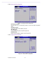
2.16
GPIO Connector (CN21)
The board supports 8-bit GPIO through GPIO connector. The 8 digital inputs and out-
puts can be programmed to read or control devices, with each input or output
defined.
2.17
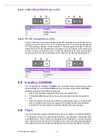
ATX Power in connector (CN23)
The PCM-3362 can support an advanced soft power switch function, if an ATX power
supply is used. please follow below instruction to enable ATX functions.
1.
Plug ATX power cable (1700002332) into CN24.
2.
Connect the 3-pin plug of this power cable to CN23 (ATX Power in connector).
3.
Connect the power on/off button cable of the chassis to CN12 (front panel con-
nector) pin1-2.
2.18
Power Connectors (CN24)
Supplies main power +5 V to the PCM-3362, and to devices that r12 V.
2.19
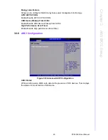
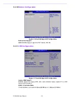
I2C Bus connector (CN25)
PCM-3362 provides I2C Bus connector for customer connection to I2C protocol
embedded device.
Advantech also provide I2C API allowing a developer to interface with an embedded
system environment and transfer serial messages using the I2C protocols, allowing
multiple simultaneous device control.
2.20
-12 V & -5 V power connector (CN26)
The PCM-3362 is equipped with a Negative Power Input connector providing -12 V &
-5 V power if your applications happen to need it.
2.21
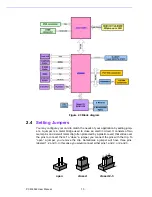
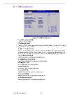
Watchdog timer configuration
An onboard watchdog timer reduces the chance of disruptions which EMP (electro
magnetic pulse) interference can cause. This is an invaluable protective device for
standalone or unmanned applications. Setup involves one jumper and running the
control software (refer to Appendix).
Caution!
Important Make sure that the ATX power supply can take at least a
10mA load on the 5 V standby lead (5VSB). If not, you may have diffi-
culty powering on your system.
Содержание PCM-3362
Страница 1: ...Data Modul AG www data modul com Specification PCM 3362 ...
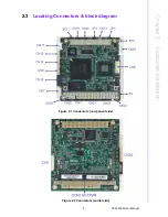
Страница 12: ...5 PCM 3362 User Manual Chapter 1 General Information Figure 1 2 Board layout Dimensions Solder Side ...
Страница 13: ...PCM 3362 User Manual 6 ...
Страница 14: ...Chapter 2 2 Hardware Installation ...
Страница 23: ...PCM 3362 User Manual 16 ...
Страница 24: ...Chapter 3 3 AMI BIOS Setup ...
Страница 44: ...Chapter 4 4 Software Introduction Installation ...
Страница 55: ...PCM 3362 User Manual 48 ...
Страница 56: ...Chapter 5 5 Chipset Software Installation Utility ...
Страница 58: ...Chapter 6 6 Integrated Graphic Device Setup ...
Страница 60: ...Chapter 7 7 LAN Configuration ...
Страница 75: ...PCM 3362 User Manual 68 ...
Страница 76: ...Appendix C C Mechanical Drawings ...
Страница 77: ...PCM 3362 User Manual 70 C 1 Board Mechanical Drawings Figure C 1 PCM 3362 Mechanical Drawing Component Side ...
Страница 78: ...71 PCM 3362 User Manual Appendix C Mechanical Drawings Figure C 2 PCM 3362 Mechanical Drawing Solder Side ...
Страница 81: ...PCM 3362 User Manual 74 ...
Страница 82: ...Appendix D D Watchdog Timer and GPIO sample code ...


