


Connecting External Devices to VME Option Boards
4-20
014–001867
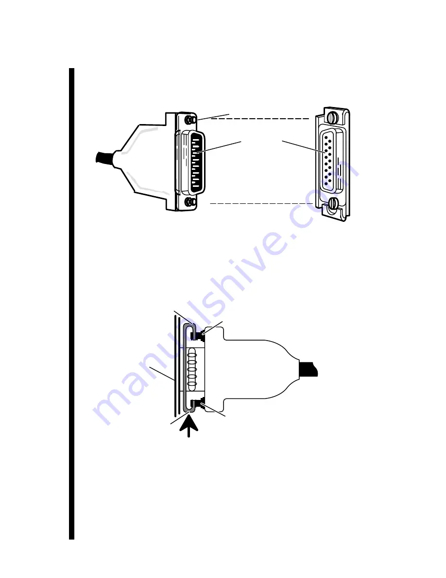
3. Align the connector pins, clip mounts, and D-shaped bevels as shown in
Figure 4–23 before gently pushing the cable connector completely over the
connector. Make certain the slide clip has not hindered a secure connection.
Slide clip
Cable connector (male)
Slide clip mounts
Connector pins
1–15
Drop cable (side view)
Figure 4–23 Aligning Slide Clip Mounts with a LAN Connector
4. Push the edge of the slide clip into position, so the small mount slot surrounds
its cable connector mount. Figure 4–24 illustrates how to secure a slide clip
connection.
Mount slot
(large)
Mount slot
(small)
VTC board
air dam
Cable connector mount
Cable connector mount
Figure 4–24 Securing a LAN Drop Cable to a VTC Connector
If you haven’t already connected the remote end of the cable to your transceiver, do
so now. Refer to the device-specific documentation for your transceiver, if necessary.
When you finish connecting all external devices to your VME option board(s), refer
to your starting manual for instructions on powering up your system. You should
then refer to your operating system documentation for instructions on what to do
after booting or rebooting your system hardware.
Содержание AViiON Series
Страница 2: ......
Страница 6: ......
Страница 12: ...Preface x 014 001867...
Страница 86: ...Configuring VME Option Boards 2 52 014 001867...
Страница 144: ...Connecting External Devices to VME Option Boards 4 44 014 001867...
Страница 150: ...VME Backplane Connector Signals and Power Distribution A 6 014 001867...
Страница 196: ...Assigning VME Data Bus and Interrupt Priorities E 10 014 001867...
Страница 206: ......
Страница 209: ...Cut here and insert in binder spine pocket Setting Up and Installing VMEbus Options in AViiON Systems 014 001867 03...
Страница 210: ...Appendix Title...


