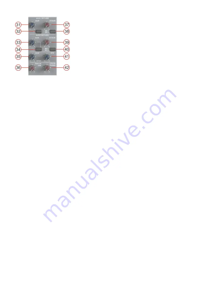
background image


14 

32. PFL switch 

Allows you to route the 

Aux 1 return (54)

 input to the PFL bus. 


33. Aux 2 return 

The signal of the (stereo) 

Aux 2 return (55)

 inputs is summed 

together for a mono  signal and is routed to the (internal) aux  
bus. This control allows you to adjust the level of the internal  
aux bus to the (mono) 

aux send (60)

 output. 


Warning: If you use the aux 2 return (55) input in combination  
with the aux send (60) output as an effect send return, make  
sure this control is set to its minimum position (fully  
counterclockwise) otherwise you will create a feedback  
loop. If you’re using this as an effect return you have to adjust  
the return level with the ST/sub (39) control. 


34. PFL switch 

Allows you to route the 

aux 2 return (55)

 inputs to the PFL bus. 


35. Aux  send


With this control


You can adjust the output level of the aux bus to the 

aux send (60)

 output. 

 
36. Tape in/USB


This control allows you to control the level of the 

tape in (62)

 and/or 

USB (67)

 input in the main (ST) mix.


37. Aux 1 ST/sub 

This control allows you to adjust the level of the (stereo) signal from the 

aux 1 return (54) 

inputs to either 

the main (ST) bus or the sub bus, depending on the position of the 

ST/sub (38)

 button. 

 
38. Aux 1 ST/sub Button  

Allows you to route the signal from the aux 1 return input (controlled by the 

ST/sub (37) control

) to either 

the main (ST) or the sub bus. 


39. Aux 2 ST/sub 

This control allows you to adjust the level of the (stereo) signal from the 

aux 2 return (55) 

inputs to either 

the main (ST) bus or the sub bus, depending on the position of the 

ST/sub (40)

 switch. 


40. Aux 2 ST/sub button 

Allows you to route the signal from the 

aux 2 return (55) 

inputs (controlled by the 

ST/sub (37)

 control) to 

either the main (ST) or the sub bus. 


41. EFX send control


With this control


You can adjust the level of the 

EFX send (61)

 output which is connected to the EFX bus. 


42. Ctrl room/phones 

This control allows you to adjust the volume of the 

control room (57)

 outputs and the 

headphones (64)


outputs. 
Depending on the type of headphones connected to the phones jack, the Powermix is capable of 
producing very high output levels via the phones output. Therefore, make sure to turn the control all the 
way down (minimum setting) before connecting the headphones. 


Warning: Listening to loud sound pressure levels over a longer period of time leads to hearing damage! 


Содержание GIG-12

Страница 1: ...GIG 12 ORDERCODE D2262 Highlite International B V Vestastraat 2 6468 EX Kerkrade The Netherlands...

Страница 2: ...P Audio for more excellent audio products We design and manufacture professional audio equipment for the entertainment industry New products are being launched regularly We work hard to keep you our c...

Страница 3: ...tructions 3 Operating Determinations 4 Return Procedure 5 Claims 5 Description of the device 6 Features 6 Overview 6 Front panel 7 Back panel 9 Installation 9 Functions 10 Connection Cables 18 Mainten...

Страница 4: ...he system To maintain perfect condition and to ensure a safe operation it is absolutely necessary for the user to follow the safety instructions and warning notes written in this manual Please conside...

Страница 5: ...y to reduce the input signal level by using the INPUT control To emphasize a frequency range you don t necessarily have to move its respective control upward try lowering surrounding frequency ranges...

Страница 6: ...method to use Note If you are given an RMA number please include the following information on a piece of paper inside the box 1 Your name 2 Your address 3 Your phone number 4 A brief description of th...

Страница 7: ...ternal input source It has inserts and low cut on the mono channels and selectable pre post aux send The stereo output is equipped with a contour function that will give your main mix extra body and a...

Страница 8: ...ol range mic 0 40dB line 25 15dB 7 Low cut filter button mono channel 1 4 8 EQ hi control range 15 15 dB 9 EQ mid control range 15 15 dB 10 EQ low control range 15 15 dB 11 Aux 1 level control 12 Aux...

Страница 9: ...33 Aux 2 return level control 34 Aux 2 to PFL button 35 Aux send level control 36 Tape in USB level control 37 Aux 1 to ST sub level control 38 Aux 1 to ST sub button 39 Aux 2 to ST sub level control...

Страница 10: ...send output 62 Stereo tape in inputs 63 Stereo record outputs 64 Stereo phones output Back panel Fig 5 65 Power on off switch 66 IEC inlet 67 USB port Installation Remove all packing materials from th...

Страница 11: ...can occur 4 Insert Insert for external device effect compressor etc The insert jack provides an output of the channels signal at line level At the same time the insert has an input at line level from...

Страница 12: ...ou to adjust the channel s level to the Aux bus 12 Channel pre post The pre post button toggles the aux 1 signal to be taken pre or post fader 13 Channel effects The Effects control allows you to adju...

Страница 13: ...room or phones output independent of the position of the channel fader 20 20 Channel fader The fader controls the volume of a single channel The channel faders should be positioned within the range o...

Страница 14: ...ght up So both balanced and unbalanced microphones can be connected Unbalanced microphones may be damaged if the phantom power is activated However unbalanced microphones are rarely to be found these...

Страница 15: ...aux 1 return 54 inputs to either the main ST bus or the sub bus depending on the position of the ST sub 38 button 38 Aux 1 ST sub Button Allows you to route the signal from the aux 1 return input con...

Страница 16: ...that the mains plug is plugged in correctly If the LED still doesn t light up please contact your DAP Audio dealer 48 LED VU meter 49 Tape USB button This button allows you to assign the VU meter to t...

Страница 17: ...you have to adjust the return level with the aux 2 ST sub 39 control 56 Stereo sub outputs Unbalanced 6 3mm jacks 57 Stereo control room outputs Unbalanced 6 3mm jacks 58 Stereo main outputs Unbalanc...

Страница 18: ...Do not supply power before the whole system is set up and connected properly 66 IEC power inlet This connector is meant for the connection of the supplied main cord Connect one end of the power cord...

Страница 19: ...s and twists when coiling them This gives the advantage of increasing their life and reliability Periodically check your cables A great number of problems faulty contacts ground hum discharges etc are...

Страница 20: ...nnections are thoroughly dry before linking equipment or supplying electric power Troubleshooting DAP Audio GIG 12 This troubleshooting guide is meant to help solve simple problems If a problem occurs...

Страница 21: ...x stereo return 10K CD Tape stereo input 10K Gain control Mono channels 50 dB Stereo channels 40 dB Aux FX 10 dB T H D 0 005 Any output 1Khz 14dBu 20Hz to 20Khz channel inputs S N 90 dB Frequency Resp...

Страница 22: ...20 Appendix 1 GIG 12 Block Diagram...

Страница 23: ......

Отзывы: