


100% will set the load to its maximum luminance. If this is not desired because it is too
bright (and wastes unneccessary energy) then the slider is adjusted to a lower setting.
-
The middle slider
has a ‘CURRENT’ light level indicator which moves (after a short
delay) according to the current lux level as read at the photocell. Once the desired
dimming level is selected by the upper slider then the maintained ‘Dimming Control
Level’ level can be set by adjusting the slider directly over the ‘CURRENT’ bar (see
diagram 33b). The circular adjuster is slightly transparent to see the exact point.
-
The lower slider
sets the ‘Threshold Light Switching Level’ ie. the lux at which the load
will automatically be switched OFF when above the set level and ON below the level.
- The switching level should ALWAYS be set slightly ABOVE (see diagram 33c) the
selected ‘Dimming Control Level’.
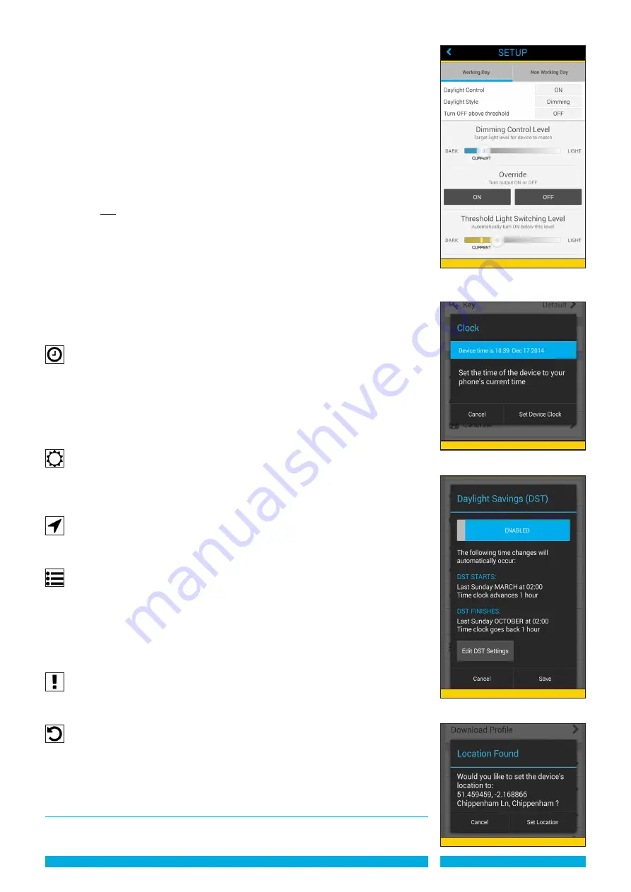
DIMMING WITh 1-10VDC BALLAST
-
If the selected MODE has ‘Daylight Control’ ON, and the dimming feature is
selected
two adjustment sliders are available to set the threshold values plus an ON/
OFF override switch.
-
The upper slider
has a ‘CURRENT’ light level indicator which moves (after a short
delay) according to the current lux level as read at the photocell.
- The desired dimming level is selected by the moving the slider above or below the
‘CURRENT’ level (see diagram 34). The ON / OFF override can assist in assessing the
CURRENT level with the load on or off (allow short delay for level to be calculated).
-
The lower slider
sets the ‘Threshold Light Switching Level’ ie. the lux at which the load
will automatically be switched OFF when above the set level and ON below the level.
- The switching level should ALWAYS be set slightly ABOVE the selected ‘Dimming
Control Level’.
Clock
- This function synchronises the device’s internal clock with the clock on your
mobile / tablet.
IMPORTANT: ThE DEVICE CLOCk BATTERy MUST BE ACTIVATED By CLICkING
ThE RED DIP SWITCh INTO ThE DOWN POSITION ON ThE CONTROLZAPP
DEVICE (SEE PRODUCT INSTRUCTIONS).
- Press ‘Clock’. New screen appears with the clock time indicated in the blue box. Press
‘Set Clock’ to synchronise. The new time appears in the blue box (See Diagram 35).
Daylight Savings
- This function allows you to offset the start and/or finish time for Daylight Savings Time
(DST) such as British Summer Time (See Diagram 36).
- Press ‘Setup Daylight Savings’. New screen appears ‘Enabled’ or select appropriate
timings then press ‘Save’ or ‘Cancel’.
Location
- Locates the device to an exact location by GPS. Press ‘Set Device Location’ (See
Diagram 37). After delay whilst finding location, new screen appears ‘Location Found’
with the co-ordinates and place name of the device. Press ‘Set Location’ or ‘Cancel’.
Log
- Allows you to overview changes made by the as a scrollable list of text. This is useful in
troubleshooting if any issues arise with a device.
- The log can be Started, Stopped and Cleared by pressing the appropriate button at the
bottom of the page.
- When Started a new screen appears ‘Select Log Level’ with 5 points at which to
interrogate the log: ‘Error’, ‘Warning’, ‘Info’, ‘Debug’ and ‘Trace’. Select the appropriate
log and the events are listed.
Test
-
This function allows you to test the lighting load is working. It switches the load ON
for 4 seconds then OFF for 4 seconds before reverting to the scheduled mode. Press
‘Test’. New screen appears ‘Test’.
Reset to default profile
-
This function returns the device to the original embedded default profile.
-
Press ‘Reset to default profile’ New screen appears ‘Reset to default profile’ requiring
confirmation ‘Are you sure you want to return this device to original embedded default
profile’. Press ‘Reset to default profile’ or ‘Cancel’.
Creating Group Settings
Group Settings override the PROFILE settings set up in the ControlZAPP device.
This function is useful when the load requires to be permanently OFF or permanently ON or
Diagram 35
Diagram 36
Diagram 37
PAGE 9
Diagram 34


