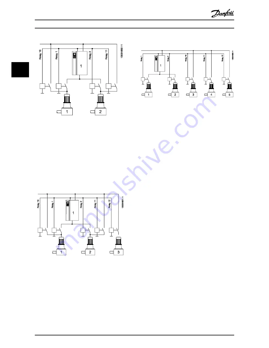
Illustration 2.9 Example 1
As
Illustration 2.9
the two pumps can be ether variable
speed or fixed speed with equal running hours.
For this configuration relay selections in parameter
group
27-7* Connections
are as follows:
27-70.0 RELAY 1
→
[8] Pump 1 to Drive 1
27-70.1 RELAY 2
→
[16] Pump 2 to Drive 1
27-70.9 RELAY 10
→
[72] Pump 1 to Mains
27-70.10 RELAY 11
→
[73] Pump 2 to Mains
27-70.11 RELAY 12
→
[0] Standard Relay
Illustration 2.10 Example 2
With equal running hours for all three pumps, pump 1 and
2 can be either variable speed or fixed speed.
For this configuration relay selections in group
27-7*
Connections
are as follows:
27-70.0 RELAY 1
→
[8] Pump 1 to Drive 1
27-70.1 RELAY 2
→
[16] Pump 2 to Drive 1
27-70.9 RELAY 10
→
[72] Pump 1 to Mains
27-70.10 RELAY 11
→
[73] Pump 2 to Mains
27-70.11 RELAY 12
→
[74] Pump 3 to Mains
Illustration 2.11 Example 3
Pumps 1 and 2 alternate each with 50% of the running
hours. The fixed speed pumps turned on and off as
needed with equal running time between them.
For this configuration relay selections in parameter
group
27-7* Connections
are as follows:
27-70.0 RELAY 1
→
[8] Pump 1 to Drive 1
27-70.1 RELAY 2
→
[16] Pump 2 to Drive 1
27-70.9 RELAY 10
→
[74] Pump 3 to Mains
27-70.10 RELAY 11
→
[75] Pump 4 to Mains
27-70.11 RELAY 12
→
[76] Pump 5 to Mains
2.2.4 Using Soft Starters for Fixed Speed
Pumps
Soft Starters can be used in place of contactors for any
configuration using fixed speed pumps.
NOTICE
Mixing Soft Starters and contactors prevents control of
output pressure during staging and de-staging
transitions. Use of soft starters delays staging due to the
ramp time of the fixed speed pump.
2.3 Sleep Mode
If the load on the system allows for stop of the motor and
the load is monitored, the motor can be stopped by
activating the Sleep Mode function. This is not a normal
Stop command, but ramps the motor down to 0 RPM and
stops energizing the motor. When in Sleep Mode, certain
conditions are monitored to find out when load has been
applied to the system again.
Activate Sleep Mode either from the Low Power
Detection/Low Speed Detection or via an external signal
applied to one of the digital inputs (must be programmed
via parameter group
5-1* Digital Inputs
). To use for
example an electro-mechanical flow switch to detect a no
Application Types
VLT
®
AQUA Drive MCO 101/MCO 102
10
MI38C402 - VLT
®
is a registered Danfoss trademark
2
2


