1.
Fasten decoupling plate to the bottom of the frequency converter with screws and washers from the accessory bag.
2.
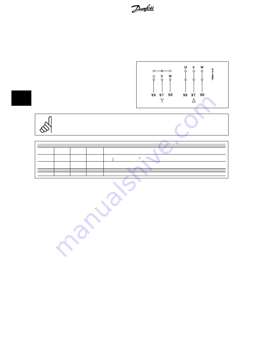
Attach motor cable to terminals 96 (U), 97 (V), 98 (W).
3.
Connect to earth connection (terminal 99) on decoupling plate with screws from the accessory bag.
4.
Insert terminals 96 (U), 97 (V), 98 (W) and motor cable to terminals labelled MOTOR.
5.
Fasten screened cable to decoupling plate with screws and washers from the accessory bag.
All types of three-phase asynchronous standard motors can be connected
to the frequency converter. Normally, small motors are star-connected
(230/400 V, D/Y). Large motors are delta-connected (400/6090 V, D/Y).
Refer to the motor name plate for correct connection mode and voltage.
NB!
In motors without phase insulation paper or other insulation reinforcement suitable for operation with voltage supply (such as a fre-
quency converter), fit a Sine-wave filter on the output of the frequency converter.
No.
96
97
98
Motor voltage 0-100% of mains voltage
U
V
W
3 wires out of motor
U1
V1
W1
6 wires out of motor, Delta-connected
W2
U2
V2
U1
V1
W1
6 wires out of motor, Star-connected
U2, V2, W2 to be interconnected separately
No.
99
Earth connection
PE
5.3.5 Motor Cables
See section
General Specifications
for correct dimensioning of motor cable cross-section and length.
•
Use a screened/armoured motor cable to comply with EMC emission specifications.
•
Keep the motor cable as short as possible to reduce the noise level and leakage currents.
•
Connect the motor cable screen to both the de-coupling plate of the frequency converter and to the metal cabinet of the motor.
•
Make the screen connections with the largest possible surface area (cable clamp). This is done by using the supplied installation devices in the
frequency converter.
•
Avoid mounting with twisted screen ends (pigtails), which will spoil high frequency screening effects.
•
If it is necessary to split the screen to install a motor isolator or motor relay, the screen must be continued with the lowest possible HF impedance.
F frame Requirements
F1/F3 requirements:
Motor phase cable quantities must be 2, 4, 6, or 8 (multiples of 2, 1 cable is not allowed) to obtain equal amount of wires attached
to both inverter module terminals. The cables are required to be equal length within 10% between the inverter module terminals and the first common
point of a phase. The recommended common point is the motor terminals.
F2/F4 requirements:
Motor phase cable quantities must be 3, 6, 9, or 12 (multiples of 3, 2 cables are not allowed) to obtain equal amount of wires
attached to each inverter module terminal. The wires are required to be equal length within 10% between the inverter module terminals and the first
common point of a phase. The recommended common point is the motor terminals.
Output junction box requirements:
The length, minimum 2.5 meters, and quantity of cables must be equal from each inverter module to the common
terminal in the junction box.
5 How to Install
VLT
®
AQUA Drive Design Guide
124
MG.20.N5.02 - VLT
®
is a registered Danfoss trademark
5
Содержание VLT AQUA Drive Series
Страница 38: ...3 VLT AQUA Selection VLT AQUA Drive Design Guide 38 MG 20 N5 02 VLT is a registered Danfoss trademark 3...
Страница 106: ...5 How to Install VLT AQUA Drive Design Guide 106 MG 20 N5 02 VLT is a registered Danfoss trademark 5...
Страница 150: ...5 How to Install VLT AQUA Drive Design Guide 150 MG 20 N5 02 VLT is a registered Danfoss trademark 5...
Страница 168: ...7 RS 485 Installation and Set up VLT AQUA Drive Design Guide 168 MG 20 N5 02 VLT is a registered Danfoss trademark 7...
Страница 194: ...8 Troubleshooting VLT AQUA Drive Design Guide 194 MG 20 N5 02 VLT is a registered Danfoss trademark 8...


