background image

82 of 132

M-SV-001-EN Rev.E

Compressor Components

Figure 77 - Connecting Leads 

to PWM Connector and HV- 

Test Point

6. Repeat Step 3 for all 10 pin holes on both PWM 
connectors.

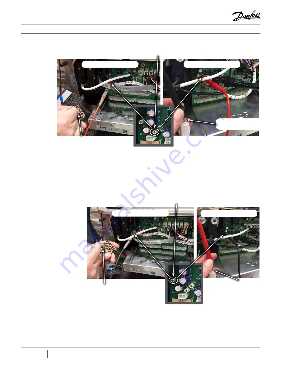
7. Still set on diode measurement, place the black 
(-) multimeter lead on the HV+ test point of the 
Backplane and the red (+) multimeter lead in 

the first pin hole of the PWM connector, ensure 
the lead makes contact with the clip in the pin 
hole. See Figure 78 (Connecting Leads to PWM 
Connector and HV+ Test Point). The measured 
voltage drop should be 0.39-0.46VDC.

8. Repeat Step 5 for all 10 pin holes of both PWM 
connectors.

9. If any of the test results are out of the 0.39 - 
0.46 VDC range, the PWM is defective and should 
be replaced.

Figure 78 - Connecting Leads 

to PWM Connector and HV+ 

Test Point

Red (+) Lead to HV-

Black (-) Lead to PWM 

Molex Connector

Black (-) Lead to PWM 

Connector

Red (+) Lead to PWM 

Connector

Red (+) Lead to PWM 

Molex Connector

Major Revision “E” and Earlier

Major Revision “F” and Later

Black (-) Lead to HV+

Major Revision “E” and Earlier

Major Revision “F” and Later

Содержание Turbocor TG230

Страница 1: ...Danfoss Turbocor Twin Turbine Centrifugal Compressors TT TG Series Compressors Service Manual http turbocor danfoss com ...

Страница 2: ...THIS PAGE INTENTIONALLY LEFT BLANK ...

Страница 3: ...e C January 2017 All Major revision F compressor changes throughout the manual D August 2017 54 57 Added IGBT Control Card Replacement instructions E October 2017 15 97 123 124 Added R513A refrigerant Updated Figure 95 SMT Tool Suite Lancher Strip Removed Appendix B Soft Start Board ...

Страница 4: ...4 of 132 M SV 001 EN Rev E THIS PAGE INTENTIONALLY LEFT BLANK ...

Страница 5: ...essor Fundamentals 22 2 1 Main Fluid Path 22 2 2 Motor and Power Electronics Cooling 22 2 3 Capacity Control 26 2 4 Compressor Energy and Signal Flow 26 Compressor Components 29 3 1 Component Identification 29 3 2 Compressor Removal and Installation 34 3 2 1 Refrigerant Containment 34 3 2 2 Compressor Removal 34 3 2 3 Compressor Installation 34 3 3 3 Phase Main Voltage Input Terminal Block 37 3 3 ...

Страница 6: ...lation 68 3 12 Solenoids and Actuators 68 3 12 1 Function 68 3 12 2 Connections 68 3 12 3 Verification 69 3 12 4 Removal and Installation 70 3 13 IGV 71 3 13 1 Function 71 3 13 2 Connections 71 3 13 3 Verification 72 3 13 4 Removal and Installation 72 3 14 BMCC 73 3 14 1 Function 73 3 14 2 Connections 73 3 14 3 Verification 74 3 14 4 Removal and Installation 74 3 15 Compressor Interface Module 75 ...

Страница 7: ...104 4 3 1 When to Calibrate the Bearings 104 4 3 2 Performing a Calibration 104 4 3 3 After Calibration is Complete 106 4 3 4 Create a Calibration Report 106 4 3 5 Calibration Report Analysis 107 4 4 Compressor Connection Status Indications 109 4 5 System and Compressor Level Troubleshooting 109 4 5 1 Compressor Voltage Troubleshooting 109 4 5 2 Determining the Cause of an Energy Drain 111 4 5 3 D...

Страница 8: ...Indicators TT350 TT400 TT500 TT700 TG310 TG390 TG520 33 Table 9 Expected AC Voltage Range 39 Table 10 SCR Diode Values 45 Table 11 SCR Gate Resistance Ranges 45 Table 12 Backplane Test Point Values 66 Table 13 Solenoid Actuator Coil Resistance Ranges 69 Table 14 Magnetic Bearing Coil Resistance Values 86 Table 15 Bearing Amperage Ranges 87 Table 16 Bearing Sensor Coil Resistance 89 Table 17 Alarm ...

Страница 9: ...e AC Input Voltage on the AC Input Terminals 38 Figure 27 Measuring 3 Phase AC Input TT300 TG230 Only 38 Figure 28 Terminal Block Bus Bars TT350 TT400 TT500 TT700 TG310 TG390 TG520 39 Figure 29 Terminal Block Bus Bars TT350 TT400 TT500 TT700 TG310 TG390 TG520 39 Figure 30 AC Input to SCRs TT300 TG230 40 Figure 31 Terminal Block Spacers 40 Figure 32 Screws Securing Terminal Block to Casting 41 Figu...

Страница 10: ...igure 84 Front Bearing 4 Pin Orientation 86 Figure 85 Front and Rear Bearing Feed Throughs with Molex Connectors 87 Figure 86 Compressor Monitor Tool 87 Figure 87 Bearing Sensor Feed Throughs 88 Figure 88 Bearing Sensor Cables 88 Figure 89 Bearing Sensor Pin Locations 89 Figure 90 Cavity Temperature Sensor Terminal 90 Figure 91 Temperature vs Resistance 90 Figure 92 Cavity Temperature Sensor Remov...

Страница 11: ...re provided AS IS without any warranty of any kind either express or implied including without limitation any implied warranties of condition uninterrupted use merchantability fitness for a particular purpose In no event shall DTC be liable for direct indirect special incidental or consequential damages arising out of the manufacture use or the inability to manufacture or use information contained...

Страница 12: ...12 of 132 M SV 001 EN Rev E THIS PAGE INTENTIONALLY LEFT BLANK ...

Страница 13: ...This manual gives only general procedures for servicing and does not provide part numbers of single products or single components If this information is required please contact a recognized Danfoss Turbocor OEM customer This manual is organized in the following manner Section 1 Introduction this section describes the purpose of the manual its organization conventions used in the manual and a safet...

Страница 14: ...ualified and trained personnel should install start up and service Danfoss Turbocor compressors Safety information is located throughout the manual to alert service personnel of potential hazards and is identified by the headings DANGER and CAUTION A DANGER notification signifies an essential operation or maintenance procedure practice or condition which if not strictly observed could result in in...

Страница 15: ...300 TG230 Before performing any service on the compressor electrical power must be isolated Before removing top side covers isolate the compressor power by completing the following steps 1 Turn off the Mains Input power to the compressor 2 Lock Out Tag Out LOTO the mains disconnect to ensure no accidental or unauthorized re application of the Mains Input power can occur 3 Remove the Mains Cover on...

Страница 16: ...utlines static control precautions that must be followed when providing service support in the field Service support personnel should create a safe static free environment Service personnel must use a commercially available service kit for handling static sensitive devices The kit typically includes Ground cord assembly Alligator clip Grounding wrist strap Wrist strap tester If a safe static contr...

Страница 17: ...Start Board clip the ESD strap ground clip to the mains plate Refer to arrow in Figure 5 Mains Plate and Ground Post 4 If you only need to remove the Service Side Cover clip the ESD strap ground to the cover screw hole that is part of the compressor housing Refer to arrows in Figure 6 Compressor Grounding Points Figure 5 Mains Plate and Ground Post Figure 6 Compressor Grounding Points Ground Point...

Страница 18: ...ess is not designed to be left in the compressor during normal operation When checks are complete disconnect and remove the test harness Refer to Figure 8 DC Bus Harness Connection Diagram for a connection diagram Figure 7 DC Bus Test Harness Diagram Figure 8 DC Bus Harness Connection Diagram DANGER Before using the DC bus test harness integrity of the fuses resistors in the harness and cable must...

Страница 19: ...roximately 100kΩ and the reading for the fuse should be 29Ω 3 Remove the Service Side Cover 4 Install the ESD clip 5 Disconnect the J1 and J7 connectors on the Soft Start Board See Figure 9 Soft Start Board 6 Connect the two plugs of the compressor cable harness into the corresponding sockets of the DC bus test harness See Figure 10 Connect Test Harness to Soft Start Board 1 9 1 Installation of th...

Страница 20: ...ble passage on either side of the HV DC DC Converter down into the service side See Figure 12 Cable Passage Figure 11 Connect Test Harness to Compressor Figure 12 Cable Passage DANGER The DC bus test harness is not designed to be left in the compressor during normal operation When checks are complete disconnect and remove the test harness 9 Reinstall the Mains Input Cover and Top Cover Cable Passa...

Страница 21: ...tput from the Soft Start Board transformer The DC lead connects to the DC bus input to the Soft Start Board 6 When finished isolate compressor power and remove the DC bus test harness 1 9 2 DC Bus Test Harness Use Table 2 Expected DC Bus Voltage Compressor Nameplate AC Voltage Acceptable AC Voltage Range Expected DC Bus Voltage Range 575 VAC 518 632 VAC 700 853 VDC 460 VAC 414 506 VAC 559 683 VDC ...

Страница 22: ...user In the second stage impeller velocity energy is again added to the refrigerant and converted to the final discharge pressure in the discharge diffuser and volute From the second stage impeller refrigerant passes as a high pressure superheated vapor to the system discharge line Liquid refrigerant having at least 2 C Kelvin 3 6 F Rankine sub cooling at connection point must be piped to the comp...

Страница 23: ...erature or the motor temperature reaches its turn on point and solenoid 2 is opened if the Inverter or silicon controlled rectifier SCR temperature reaches its turn on point Medium temperature MT version compressors require their motor cooling suction line to be vented externally to the main suction line through an evaporator pressure regulating EPR valve This valve is required to ensure that evap...

Страница 24: ...24 of 132 M SV 001 EN Rev E Compressor Fundamentals Figure 15 Compressor Motor and Power Electronics Cooling TT300 TG230 Serial Cooling ...

Страница 25: ...25 of 132 M SV 001 EN Rev E Compressor Fundamentals Figure 16 Compressor Motor and Power Electronics Cooling All Models Except TT300 TG230 Serial Cooling ...

Страница 26: ... operation Speed modulation is achieved by the use of Inverter control To accomplish this the incoming 3 phase AC supply is converted to high voltage DC incorporating smoothing storage capacitors and then switched by the Inverter utilizing 3 phase rectifiers to give a simulated 3 phase AC supply of variable voltage and frequency to the compressor motor During normal operation 3 phase power is requ...

Страница 27: ...DC bus voltage from the SCRs charges the capacitors 5 DC bus provides DC voltage to Inverter 6 The Inverter converts the DC bus voltage into a variable frequency 3 phase simulated AC voltage to the Stator 7 The HV DC DC Converter uses the DC bus voltage to provide 24VDC and 250VDC to the Backplane 8 The Backplane connects and supplies low DC voltage to the service side components Refer to Figure 1...

Страница 28: ...28 of 132 M SV 001 EN Rev E Compressor Fundamentals Figure 18 Compressor Energy and Control Flow Block Diagram ...

Страница 29: ...Support Base 2 Cable Harness Sensor 13 Top Access Cover 3 Suction Pressure Temperature Sensor 14 Lift Anchor Rear 4 Inlet Guide Vanes IGV Suction Port 15 End Bell 5 IGV Position Indicator 16 Motor Cooling Connection 6 IGV Housing 17 Motor Cooling TT300 TG230 and Power Electronics Cooling TT350 TT400 TT500 TT700 TG310 TG390 TG520 Access Port 1 NOTE TT300 TG230 have only one access port 7 Front Supp...

Страница 30: ...300 TG230 No Component No Component 1 Compressor I O Board 7 Bearing Motor Compressor Controller BMCC 2 Soft Start Board 8 Bearing Pulse Width Modulation PWM Amplifier 3 Insulated Gate Bipolar Transistor IGBT Inverter 9 Silicon Controlled Rectifier SCR 4 High Voltage HV DC DC Converter 10 DC Capacitor Assembly 5 Backplane 11 Fast Acting Fuses TT300 TG230 only 6 Serial Driver ...

Страница 31: ...TG230 No Component No Component 1 Discharge Temperature Pressure Sensor 6 Suction Temperature Pressure Sensor 2 Motor Winding Sensors 7 Inlet Guide Vanes IGV Position Indicator 3 Motor Cooling Solenoids 8 Bearing Sensor Ring Cable Front 4 Bearing Sensor Ring Cable Rear 9 PWM Current Output Front Bearing 5 Bearing Pulse Width Modulation PWM Current Output Rear Bearing ...

Страница 32: ...ation Covers Off TT350 TT400 TT500 TT700 TG310 TT390 TT520 No Component No Component 1 Compressor I O Board 6 Serial Driver 2 Soft Start Board 7 Bearing Motor Compressor Controller BMCC 3 Insulated Gate Bipolar Transistor IGBT Inverter 8 Bearing Pulse Width Modulation PWM Amplifier 4 High Voltage HV DC DC Converter 9 Silicon Controlled Rectifier SCR 5 Backplane 10 DC Capacitor Assembly ...

Страница 33: ...350 TT400 TT500 TT700 TG310 TG390 TG520 No Component No Component 1 Discharge Temperature Pressure Sensor 5 Bearing Sensor Ring Cable 2 Motor Winding Sensors 6 Suction Temperature Pressure Sensor 3 Motor Cooling Solenoids 7 Inlet Guide Vanes IGV Position Indicator 4 Bearing Pulse Width Modulation PWM Amplifier Current Output 8 Bearing Sensor Ring Cable Front 9 PWM Current Output Front Bearing ...

Страница 34: ... standards using dry nitrogen 10 Disconnect the compressor from the refrigerant system connections suction discharge economizer and motor cooling line taking care when removing connections that there is no residual pressure 11 Reinstall the Mains Input Cover 12 Remove the four compressor mounting bolts and associated hardware 13 Connect an appropriate lifting device to the eyebolts provided on eac...

Страница 35: ...e compressor to appropriate pressure and industry accepted standards 19 Evacuate compressor to appropriate pressure and industry accepted standards 20 Charge the compressor with refrigerant 21 Apply power to the compressor To minimize refrigerant leak potential the Motor Cooling Adapter NPT to flare connection has been replaced by a fitting incorporating all O ring seals for all Major Revision E a...

Страница 36: ...st be brazed into the braze sleeve 2 Remove pressure from compressor as per OEM standard procedure 3 Remove nut from connection fitting body Discard blanking disc Locate braze sleeve and clean Ensure removal of all oil and surface debris Braze as for standard OEM process for copper steel joint 4 Place appropriate length of 1 2 inch copper tube into braze sleeve Pretreat flux joint area as per OEM ...

Страница 37: ... any reason clean the O ring fitting and housing threads and apply a small amount of O ring lube before reassembly The terminal block is the location where the compressor receives 3 Phase AC voltage even when not running All compressors must be fitted with class T fast acting fuses to protect the solid state Inverter Danfoss Turbocor control does NOT directly measure 3 phase power values All 3 pha...

Страница 38: ...erminals and Figure 27 Measuring 3 Phase AC Input Repeat for all AC input terminals Repeat on load side of the fuses TT300 TG230 only 4 Verify that the meter shows the expected AC measurement within the range as indicated in Table 9 Expected AC Voltage Range The acceptable AC input voltage range is 10 of the nameplate AC input voltage 3 3 3 Verification 3 3 3 1 3 Phase AC Input Verification 3 3 3 ...

Страница 39: ... Range AC Input Nameplate Voltage Acceptable Voltage Range 575VAC 518 to 632VAC 460VAC 414 to 506VAC 400VAC 360 to 440VAC 380VAC 342 to 418VAC 1 Isolate the compressor power as described in the Electrical Isolation of the Compressor section of this manual 2 Disconnect the main input cables from terminal blocks 3 Disconnect the three connectors of the Soft Start Cable Harness from the bus bars 4 Re...

Страница 40: ...rews from the terminal block adaptors and lift away the fuse assemblies and insulating Mylar See Figure 30 AC Input to SCRs TT300 TG230 5 Remove the screws that secure the terminal block to the casting and remove the terminal block Compressor Components Figure 30 AC Input to SCRs TT300 TG230 Figure 31 Terminal Block Spacers 3 3 4 3 Terminal Block Installation TT350 TT400 TT500 TT700 TG310 TG390 TG...

Страница 41: ...t Make note of the Soft Start Cable Harness locations See Figure 25 Main AC Input Terminal The Soft Start Board limits in rush current when power is applied to the compressor by progressively increasing the conduction angle of the voltage through the SCRs to charge the DC capacitors It uses a 3 phase voltage input at 50 60Hz between 380 575VAC and a DC voltage signal from the SCR output to generat...

Страница 42: ...f the 15VAC supply is not present at start up the DC DC converter will not function 1 Isolate the compressor power as described in the Electrical Isolation of the Compressor section of this manual 2 Remove the screws that secure the Soft Start mounting bracket to the compressor 3 Lift the Soft Start and turn it over placing it board side up on the AC bus bars 4 Using a multimeter set for resistanc...

Страница 43: ... position 2 Secure the screws that hold the mounting bracket to the compressor Tighten to 5Nm 3 6 ft lb 3 Connect the cable connectors to the Soft Start Board 4 Connect the Soft Start ground wire to the ground post on the compressor housing Tighten to 7Nm 5 ft lb See Figure 34 Mains Input 5 Connect the Mains Input ground to the ground post Tighten to 15Nm 11 ft lb 6 Replace topside covers the DC D...

Страница 44: ...1 35 times that of the AC input voltage 460 900VDC See Figure 35 SCR Connections to locate the connections to the SCRs 1 AC input voltage to SCR 2 SCR Gate cables to Soft Start 3 SCR to DC bus Figure 35 SCR Connections TT300 left TG230 right 3 5 3 1 Diodes Verification NOTE A faulty SCR module can cause the DC bus and Mains Input current to be imbalanced This can stress the Inverter and Stator If ...

Страница 45: ...described in the Electrical Isolation of the Compressor section of this manual 2 Using needle nose pliers carefully remove the SCR gate cable harness from the SCRs 3 Using a multimeter set for resistance measurements place the leads on the two gate terminals The value should be between 1 to 25Ω 4 Reverse the leads The measured value should be the same NOTE These values can vary depending on the me...

Страница 46: ...d Figure 38 DC Bus Components Identification 5 Remove the screws that secure the SCRs to the cooling manifold 6 Lift off the SCRs from the cooling manifold and wipe clean the heat sink paste 1 Isolate the compressor power as described in the Electrical Isolation of the Compressor section of this manual 2 Using needle nose pliers carefully remove the SCR gate cable harness from the SCRs 3 Remove th...

Страница 47: ...ture sensor into the SCR manifold 2 TT300 TG230 Only Lift the SCR manifold and route the SCR temperature sensor cable under the SCR manifold 3 TT300 TG230 Only Tighten the Inverter manifold screws 4 Connect the SCR temperature sensor connector to the cable harness 5 Install the DC bus and snubber capacitors See Figure 38 DC Bus Components Identification 6 Install the terminal block and AC Mains In...

Страница 48: ...educe noise associated with the Inverter switching frequency Bleed resistors are used to discharge the capacitors after power is removed to allow the compressor to be serviced safely See Figure 38 DC Bus Components Identification for location of the DC bus components Figure 38 DC Bus Components Identification CAUTION The DC Bus Capacitor Assembly should not be disassembled Bleed resistors bus bars...

Страница 49: ...ured value should be 0 42μF to 0 52μF 1 Isolate the compressor power as described in the Electrical Isolation of the Compressor section of this manual 2 Remove the Soft Start and the Soft Start Cable Harness See Figure 39 Soft Start Cable Harness to DC Bus 4 Using a multimeter set for resistance measurement place the leads on each of the bleed resistor terminals The measured value should be betwee...

Страница 50: ...0 TT400 TT500 and TT700 only 5 Remove main AC bus bars TG310 TG390 TG520 TT350 TT400 TT500 and TT700 only 6 Remove the screws that secure the DC bus bars to the SCRs TG310 TG390 TG520 TT350 TT400 TT500 and TT700 only 7 Remove the snubber capacitors 8 Remove the nylon nuts at the base of the DC Capacitor Assembly located under the main compressor housing 9 Lift out the DC capacitors and DC bus as a...

Страница 51: ...T500 TT700 TG310 TG390 and TG520 only See right side of Figure 39 Soft Start Cable Harness to DC Bus 7 Install the main AC bus bars TT350 TT400 TT500 TT700 TG310 TG390 and TG520 only 8 Using needle nose pliers carefully install the SCR gate cable harness TT350 TT400 TT500 TT700 TG310 TG390 and TG520 only 9 Connect the SCR DC bus bars to the capacitor DC bus bars TT300 TG230 only See Figure 40 Remo...

Страница 52: ...24VDC and gating signals to the Inverter from the BMCC In return the Inverter sends current temperature error and DC bus voltage information to the BMCC via the Backplane Motor currents and voltages displayed in the SMT cannot be directly compared or correlated to incoming 3 phase AC values In the event of a 3 phase voltage power loss while the compressor is running the Inverter switches to Genera...

Страница 53: ...See Figure 44 Inverter Connections 7 Keeping the red multimeter lead on the phase 1 AC terminal place the black multimeter lead on the DC terminal The measured value should be open See Figure 44 Inverter Connections 8 Place the black multimeter lead on the phase 1 AC terminal and the red multimeter lead on the DC terminal and record the results The measured value should be open See Figure 44 Inver...

Страница 54: ...t connect the motor bus bars to the Inverter Important Do not remove the screws that secure the Inverter to the compressor main housing 7 Unscrew the six 6 screws using a T15 Torx bit Begin on the outside and work towards the center This section details the steps to remove and install the IGBT Control Card all models except for the TT300 TG230 and also the entire Inverter assembly If the Inverter ...

Страница 55: ... are two 2 different length spring pins if any are replaced be sure to replace with the same length spring pin Figure 47 Long Spring Pin Locations identifies the location of the long spring pins all other spring pins are short Figure 48 Spring Pin Identification iden tifies the difference between the two different spring pin lengths Long Spring Pins CAUTION Do not move or touch any spring pins unl...

Страница 56: ...d over the IGBT module with the connector towards motor stator output bus bar the shape of Driver Board must be aligned with IGBT Press Plate shape 7 Insert the screws into the corresponding Press Plate holes 8 Moving in a vertical direction only lower the Driver Board down on the IGBT module do not allow for any lateral movement CAUTION Any lateral movement may damage the spring pins Figure 51 Dr...

Страница 57: ...d same se quence as previous step to 1 5 Nm 13 2 in lbs Figure 53 Final Torque NOTE It is recommended to verify Inverter functionality using an inverter tester prior to reassembly of the top side electronics 11 Install the copper tubes that connect the motor bus bars to the Inverter 12 Connect the ribbon cable from the Inverter 13 Install the DC capacitor and bus assembly 14 Install the Mains Inpu...

Страница 58: ...igerant Isolation and recovery of the refrigerant must be performed by a qualified service technician adhering to industry ASHRAE standards Figure 54 Removing the Inverter TT300 TG230 Shown 3 7 4 2 Inverter Installation 1 Clean the O ring groove in housing 2 Install the O ring into the groove of the main compressor housing 3 Carefully install the Inverter 4 Install the SCR cooling manifold TT350 T...

Страница 59: ...e to the total separation of the motor windings from the incoming 3 phase current by the DC conversion Therefore the bulk of protection is based on measurements taken by the Inverter and calculations derived from those measurements Motor currents and voltages displayed in the SMT cannot be directly compared or correlated to incoming 3 phase AC values All Stators employ overheat cutout protection u...

Страница 60: ...or resistance measurements place the red multimeter lead on one of the three motor bus bars and the black multimeter lead on another motor bus bar and record the results The measured value should be less than 1Ω but not zero If the measured value is 0 0Ω or greater than 1Ω then the Stator winding is faulty and the compressor must be replaced 5 Repeat Step 4 for the remaining combinations of motor ...

Страница 61: ...61 of 132 M SV 001 EN Rev E Compressor Components Figure 56 Stator Thermistor R T Curve 1 ...

Страница 62: ...ing PWM Amplifier DC bus voltage 460 900VDC is supplied to the HV DC DC converter through the Soft Start Board F1 fuse The Soft Start Board also powers the HV DC DC Converter with 15VAC when the DC bus has reached minimum level See Figure 57 DC DC Converter Connections for the HV DC DC Converter input output I O connections Inputs 1 J1 HV DC Bus 2 J4 15VAC Outputs 3 J2 250VDC 4 J3 24VDC Figure 57 ...

Страница 63: ...C DC Converter Connections The result should not be 0 0Ω The result can be open or 150kΩ 4 Reverse the multimeter leads on the J1 plug terminals See Figure 57 DC DC Converter Connections The result should not be 0 0Ω The result can be open or 150kΩ 5 Place the multimeter leads in the J4 15VAC input terminals See Figure 57 DC DC Converter Connections The result should be 1MΩ 6 Reverse the multimete...

Страница 64: ...he Inverter plate See Figure 59 HV DC DC Converter Removal 4 Plug in all connectors to the HV DC DC Converter 5 Install the Soft Start 3 10 Backplane 3 10 1 Function The Backplane is powered by 24VDC with respect to 0V from the HV DC DC Converter The HV DC DC Converter also provides the Backplane with HV 250VDC with respect to HV for the Bearing PWM Amplifier The Backplane connects the onboard plu...

Страница 65: ...rial Driver Connection Port J2 and J3 BMCC Connection Port J1 PWM Connection Port 0V Test Point 15V Test Point 24V Test Point 5V Test Point 15V Test Point J16 Motor Cooling Solenoids Control Port J17 SCR Temperature Sensor Port J18 Suction Temperature Pressure Sensor Port J19 Discharge Temperature Pressure Sensor Port IGBT Ground Screw J20 Motor Winding Sensor Port J11 and J12 Rear Bearing Sensor ...

Страница 66: ...s functioning correctly NOTE The test point LEDs are ON if any voltage is present The test points must be measured to determine the actual voltage CAUTION The Inverter cable must be connected to the Backplane J6 if the BMCC is removed and power is applied to the compressor Table 12 Backplane Test Point Values Test Point Test Point Reference DC Voltage Range Minimum Resistance HV HV 220 to 280 250Ω...

Страница 67: ...f the Backplane All components that communicate with the Serial Driver are connected to the Backplane See Figure 60 Backplane Connections and Test Points 1 Remove the Service Side Cover 2 With main power on using a multimeter set for DC voltage measurements verify the voltage on the Backplane 15V and 24V test points as defined in Table 12 Backplane Test Point Values See Figure 60 Backplane Connect...

Страница 68: ... and or electronics cooling path The solenoid actuator coils control the opening and closing of the solenoids Solenoids are secured to the service side of the compressor housing in the upper left See Figure 63 Cooling Valve Bodies Solenoid orifice size will vary between compressor models The size can be identified by reading the number stamped into the solenoid orifice body For solenoid identifica...

Страница 69: ...r Cooling Solenoid place the meter probes at Pins 1 and 3 of the cable connector See Figure 65 Motor Cooling Solenoid Cable Connector 7 To measure the resistance across the right Motor Cooling Solenoid place the meter probes at Pins 5 and 6 of the cable connector See Figure 65 Motor Cooling Solenoid Cable Connector Figure 64 Motor Cooling Solenoid Actuators Table 13 Solenoid Actuator Coil Resistan...

Страница 70: ...lenoid actuator coils 6 Remove the solenoid body and cooling valve orifice 1 Lubricate a new O ring with O ring lubricant and install it on the valve 2 Insert the valve orifice and solenoid body in the opening and engage the first few threads by hand 3 Tighten the valve using a socket and driver 4 Leak test compressor to appropriate pressure and industry accepted standards 5 Evacuate compressor to...

Страница 71: ...V connections 3 13 IGV 3 13 1 Function 3 13 2 Connections The IGV assembly consists of movable vanes and a motor The IGV assembly is a variable angle guiding device that is used to control the capacity at low load conditions The IGV position can vary between approximately 0 closed perpendicular to flow and 100 open parallel to flow The vane angle is determined by the BMCC and controlled by the Ser...

Страница 72: ... the compressor 3 Open the Compressor Configuration tool Set the Compressor Control Mode to Manual Control by selecting Manual Control from the Compressor Control Mode drop down list 4 Open the Compressor Monitor tool 5 In the IGV Open Percentage parameter box input 110 6 On the Backplane there are four LEDs that should light up when the IGV Motor is being driven See Figure 61 LED Locations Check ...

Страница 73: ...tandards 6 Reconnect the cable at the feed through connector on the IGV Housing 7 Secure the connector clamp 8 Reconnect the suction sensor connector 4 Recover the refrigerant from the compressor 5 Disconnect the cable at the suction sensor See Figure 67 IGV Connections 6 Remove the bolts that secure the IGV assembly to the compressor housing See Figure 67 IGV Connections 7 Pull the IGV assembly a...

Страница 74: ... to the Backplane b The I O cable connection between the Backplane and the Compressor I O Board is properly attached c The cable connection between the Compressor I O Board RS485 or RS232 and the user interface user PC or chiller controller is properly attached d Inspect Backplane for indication of damage 4 Cycle power and reattempt communication with the compressor 3 14 4 Removal and Installation...

Страница 75: ... Calibration Figure 71 Compressor Interface Module Ports Figure 72 Compressor Interface Module Jumper Locations 3 15 Compressor Interface Module 3 15 1 Function 3 15 2 Connections The Compressor Interface Module CIM also referred to as the Compressor I O Board allows the user to control the compressor and allows the compressor to return status and sensor information to the user See Figure 71 Compr...

Страница 76: ... when no sensor connected Refer to the Applications Manual for thermistor specifications J4 EXV 1 EXV 2 Control 15V output EXV1 Pin 6 to 9 EXV2 Pin 1 to 4 J5 Liquid Level input LIQ LEV 1 Pin 4 to 6 Liquid level sensor driving the electronic expansion valve1 EXV1 LIQ LEV 2 Pin 1 to 3 Liquid level sensor driving the electronic expansion valve2 EXV2 Refer to the Applications Manual for further inform...

Страница 77: ...the computer 3 Open the SMT software and select the Compressor Connection Manager tool See the Service Monitoring Tools User Manual for use instructions 4 Click Connect If the Compressor Connection Manager is able to connect to the compressor the BMCC is able to communicate with the user interface If the system is not able to connect verify The D9 green LED is on The cable connection between the B...

Страница 78: ...rlock Status states Open the interlock circuit is damaged and the BMCC needs to be replaced 9 Isolate compressor power 10 Remove the J2 connector from the CIM 11 Using a multimeter for resistance measurement Place the meter probes on I LOCK and I LOCK Resistance should be 22 2kΩ if not the interlock circuit is damaged and the BMCC needs to be replaced 1 Isolate compressor power and wait for the D9...

Страница 79: ...ssor I O Board Installation Figure 74 Bearing Control Signal Flow 3 16 Bearing Pulse Width Modulator Amplifier 3 16 1 Function The PWM Amplifier supplies current to the radial and axial magnetic bearing coils as commanded by the BMCC In return the PWM passes feedback from the current sensor for the bearing coils to the BMCC See Figure 74 Bearing Control Signal Flow The Backplane provides the PWM w...

Страница 80: ...se differences The 6 pin wire connects to the rear left bearing power feed through The 4 pin wire connects to the front right bearing power feed through See Figure 75 Bearing Power Feed Throughs and PWM Connection Port and Figure 76 Bearing Pulse Width Modulator Amplifier Figure 75 Bearing Power Feed Throughs and PWM Connection Port Figure 76 Bearing PWM Amplifier J1 PWM Connection Major Revision ...

Страница 81: ...ckplane 2 Verify the bearing coil resistances are within specification 3 Verify the bearing sensor resistances are within specification 4 Perform a bearing calibration using the SMT To verify the diode sets within the PWM channels complete the following steps 1 Isolate compressor power 2 Remove the Service Side Cover verifying the LEDs on the Backplane have turned off 3 Unplug the 250VDC input J4 ...

Страница 82: ...See Figure 78 Connecting Leads to PWM Connector and HV Test Point The measured voltage drop should be 0 39 0 46VDC 8 Repeat Step 5 for all 10 pin holes of both PWM connectors 9 If any of the test results are out of the 0 39 0 46 VDC range the PWM is defective and should be replaced Figure 78 Connecting Leads to PWM Connector and HV Test Point Red Lead to HV Black Lead to PWM Molex Connector Black ...

Страница 83: ...re 79 Removing the PWM Amplifier 7 Pull the bearing PWM amplifier from J1 of the Backplane Figure 79 Removing the PWM Amplifier 3 16 4 2 PWM Amplifier Installation 1 Check that the ground screw at the lower right of the Backplane is tight before replacing the PWM 2 Align the heat sink of the PWM with the two guide pins in the main compressor housing 3 Insert the PWM into the J1 connector of the Ba...

Страница 84: ...aft position within 0 0003 7 microns One axial Z axis and two radial X Y axis magnetic bearings are used to maintain shaft position See Figure 80 Radial Magnetic Bearings and Figure 72 Axial Magnetic Bearing Centered rotation is instantaneously self corrected and maintained by the bearing control loop See Figure 65 Bearing Control Signal Flow When not powered the shaft is supported by carbon compo...

Страница 85: ...r power 2 Remove the Service Side Cover verifying the Backplane LEDs have turned off 3 Remove the Serial Driver BMCC and PWM 4 Set multimeter for resistance checks 5 Test resistance on bearing power feed through pins defined in Table 14 Magnetic Bearing Coil Resistance Values See Figure 83 Rear Bearing 6 Pin Orientation TT300 Serial Numbers 081015110 Only Figure 83 Rear Bearing 6 Pin Orientation T...

Страница 86: ... 3 25Ω 2 70 3 25Ω Axial Coil 3 4 5 70 6 20Ω TT300 TG230 only 6 00 6 70Ω TT400C E F TG390 only 6 00 6 70Ω Front Bearing Connector Front Radial Coil 1 2 2 70 3 25Ω 4 70 5 20Ω 3 4 2 70 3 25Ω 4 70 5 20Ω Notes See Figure 74 75 and 76 for pin locations All resistance values are in ohms Resistance to ground and between coils should be 100MΩ 1KV Figure 83 Rear Bearing 6 Pin Orientation TT300 Serial Number...

Страница 87: ...es displayed are within the range defined in Table 15 Bearing Amperage Ranges during compressor operation Table 15 Bearing Amperage Ranges Bearing Position Force Range Axial Force 1 to 1 Amp Front X Force 1 to 1 Amp Front Y Force 1 to 1 Amp Rear X Force 1 to 1 Amp Rear Y Force 1 to 1 Amp NOTE The above amperage ranges are a general observation It is possible to operate outside this range Figure 85...

Страница 88: ... the Bearing Sensor feed throughs located above the front and rear bearing power feed throughs See Figure 87 Bearing Sensor Feed Throughs The bearing sensor feed throughs are connected to the bearing sensor cables which connect to J9 and J10 on the Backplane See Figure 88 Bearing Sensor Cables Figure 87 Bearing Sensor Feed Throughs Figure 88 Bearing Sensor Cables Rear Bearing Sensor Feed Through R...

Страница 89: ...earing sensor feed through is in question isolate the compressor recover the refrigerant remove the feed through and repeat the above steps directly at the internal sensor connector Figure 89 Bearing Sensor Pin Locations Table 16 Bearing Sensor Coil Resistance Pin Combination Front Sensor Rear Sensor 5 2 2 0Ω to 3 5Ω 2 0Ω to 3 5Ω 5 3 2 0Ω to 3 5Ω 2 0Ω to 3 5Ω 6 7 2 0Ω to 3 5Ω 2 0Ω to 3 5Ω 6 8 2 0Ω...

Страница 90: ...stance between the Cavity Temperature Sensor terminals 1 and 3 See Figure 90 Cavity Temperature Sensor Terminal The Cavity Temperature Sensor is a 10KΩ 77 F 25 C NTC thermistor The resistance value should correspond to Figure 91 Temperature vs Resistance 6 Measure the resistance of the Cavity Temperature Sensor terminals 1 and 3 to ground See Figure 90 Cavity Temperature Sensor Terminal The resist...

Страница 91: ...perature sensor See Figure 92 Cavity Temperature Sensor Removal 1 Skip this step for all compressors that are Major Revision E and later Apply a refrigerant safe thread sealant to the cavity temperature sensor threads avoid thread locking substances 2 Insert the sensor and engage the first few threads by hand 3 Tighten the sensor to 13 Nm 9 5 ft lb 4 Leak test compressor to appropriate pressure an...

Страница 92: ...e compressor power 2 Remove the Service Side Cover 3 Disconnect the pressure temperature cable clip SUCTION J18 or DISCHGE J19 from the Backplane board See Figure 93 Pressure Temperature Cable Terminals 4 Using a multimeter set for resistance measurements place leads on Terminal 1 and Terminal 2 of the pressure temperature cable clip See Figure 93 Pressure Temperature Cable Terminals The temperatu...

Страница 93: ...n of this manual 2 Isolate the compressor recover the refrigerant according to industry standards 3 Disconnect the sensor connector 4 Using a deep socket remove the sensor 1 Check and clean O ring housing thread and O ring sealing surface in compressor housing Apply lube to O ring 2 Insert the sensor and engage the first few threads by hand 3 Using a deep socket tighten the sensor to 10 Nm 7 3 ft ...

Страница 94: ...its will stop the compressor in 10 seconds or less See Table 18 Compressor Fault Types Table 19 Motor Fault Types and Table 20 Bearing Fault Types Table 17 Alarm Types Compressor Alarm Description Inverter Temperature The measured Inverter temperature has exceeded the alarm limit Discharge Temperature The measured discharge temperature has exceeded the alarm limit Suction Pressure The measured suc...

Страница 95: ...ng fault type is present then the generic compressor fault is triggered This is not an actual fault only an indication that a motor or bearing fault has occurred Sensor Fault If the following measured temperatures in C or pressures in kPa abs are surpassed a sensor fault is triggered Inverter Temperature 100 or 0 C Cavity Temperature 100 or 20 C Suction Temperature 100 or 30 C Discharge Temperatur...

Страница 96: ...rs reading the data table from the EEPROM Generator Mode Active At greater than 0 RPM and DC bus voltage low Generator mode is enabled switching the Inverter to rectifier function to maintain the DC bus voltage until the shaft comes to a stop and delevitates SCR Ripple Voltage Fault The DC bus voltage ripple exceeds the SCR Voltage Ripple Fault limit System in Startup mode The compressor initializ...

Страница 97: ...configure the electronic expansion valve configuration parameters and settings Logged Event and Fault Viewer Retrieve logged fault and event data history regarding the operation of a connected compressor for the purpose of troubleshooting and diagnostics Compressor Data Recording and Playback Start and stop recording of all variables on the BMCC as well as launch a server partially simulating an a...

Страница 98: ...he root cause of fault occurrence Downloading fault and event logs every time a compressor is visited is useful for documenting compressor operational history Fault and event history can be extracted from the compressor memory in the SMT Logged Event and Fault Viewer tool See the latest Service Monitoring Tools User Manual for user instructions Active compressor fault and alarm messages can be vie...

Страница 99: ...o 0 and afterwards to a value greater than 0 Now the fault is reset and the compressor is ready to run The assumption is that the cause of the fault has been rectified A fault demanding a power cycle Lock Out Fault is resettable by cycling the mains power to the compressor The assumption is that the cause of the fault has been rectified See Table 22 Compressor Faults Figure 96 Fault Trigger Method...

Страница 100: ...t the time of fault Results in an Instantaneous Lock Out Fault 3 Phase Over Current Fault AFT Indicates the compressor is drawing current greater than the 3 Phase Current Fault Limit Review the fault log for recorded 3 Phase Current level demand entering air water temperature if available and other conditions that are recorded at the time of fault Usual causes are Start speed set too high particul...

Страница 101: ...s and repair as necessary Cycle power to clear Lock Out Fault Active alarm Fault Viewer in SMT allows the Lock Out counter to be monitored High Winding Temperature Fault AFT Indicates the Raw Motor Thermal Readout in the Compressor Monitor Tool has exceeded the maximum limit Ensure the liquid motor cooling line has sufficient liquid supply and is not blocked Prevent prolonged operation at a pressu...

Страница 102: ... Out Fault will occur Verify the Inverter and the Inverter cable connections See Section 3 7 3 1 If the Inverter Error fault persists after the Inverter is verified it should be replaced Review the Fault and Event Log for recorded occurrences of this fault Any occurrence of Single Phase Over current Back EMF is Low or Rotor May Be Locked faults immediately following an Inverter Error fault most li...

Страница 103: ...e incoming AC phases Measure the difference in current and voltage between the phases If there is a current imbalance more than 5 between the phases verify the incoming AC power supply Review the Compressor Monitor Tool for SCR Voltage Ripple readings at the time of the fault Phase imbalance can be caused by a faulty SCR SCR Gate Gate control from the Soft Start Board or a faulty power capacitor V...

Страница 104: ...ated to be identical to Latest values Cycle power to the compressor ensuring the green LED on the I O board turns off This may need to be repeated multiple times Create a calibration report before any change is made and after each calibration Ensure the shaft levitates correctly by clicking Validate after calibration values have been saved to EEPROM Interlock must be open RS485 or other external c...

Страница 105: ... determine the cause of failure verify the following Ensure there are no faults present the shaft will not levitate for validation if a fault is present Ensure the RS485 at J1 on the I O board is disconnected from external communication if the chiller controller automatically sets the control mode it will stop the calibration process prematurely Ensure Interlock is open Figure 97 Bearing Calibrati...

Страница 106: ...riginal factory calibration values stored in EEPROM to the latest calibration allows determination of long term changes Saving to EEPROM permanently overwrites existing stored calibration values Stored values are used for startup check at the next power cycle The previous values cannot be recovered once the new values are saved to EEPROM Original calibration values should only be overwritten when ...

Страница 107: ...ation is disconnected Action Verify the PWM Action Verify the bearings Action Verify the bearing sensors 4 Data in Report One or more of the gain values exceeds 3 0 Interpretation Bearing electrical fault or shaft is obstructed Action Verify the bearings Action Verify the bearing sensors See Figure 98 Bearing Calibration Flow 5 Data in Report One or more of the bearing Force Current values exceeds...

Страница 108: ...date shaft create a calibration report and cycle power Do not save calibration to EEPROM Create a calibration report Return compressor to normal operation No Yes No Successful Re Calibration Return compressor to normal operation Shaft is obstructed or bearing system issue Verify the bearings Verify the bearing sensors Yes Verify the PWM If verification passes but the bearings cannot be validated r...

Страница 109: ...f the nameplate rated voltage restore correct voltage 3 Verify all three phases of voltage after the mains fuses If the name plate rated voltage is present proceed to Step 4 If any of the three phases are not present isolate compressor power then replace the fuses 4 Isolate the compressor power as described in the Electrical Isolation of the Compressor section of this manual 5 Inspect all electron...

Страница 110: ...n 3 11 4 1 BMCC see Section 3 14 4 1 and PWM see Section 3 16 4 1 22 Re apply compressor power 23 Verify the HV and the 24 VDC test points on the Backplane If all voltages are within 10 proceed to Step 26 If either voltage is not within 10 isolate compressor power and wait for the LED s on the Backplane to go out then disconnect the J4 and J24 connectors from the Backplane 24 Re apply compressor p...

Страница 111: ...in 10 the BMCC is not draining energy If any of these voltages are not within 10 proceed to Step 5 5 Isolate the compressor power and wait for the LEDs on the Backplane to turn off 6 Remove the BMCC see Section 3 14 4 1 ensure the Inverter cable remains connected 7 Re apply the compressor power 8 Test the Backplane voltages at the 24V 15 5 and the 15 VDC test points If all voltages are within 10 t...

Страница 112: ... voltage input see Section 3 9 3 1 b Verify the DC DC Converter see Section 3 9 3 c Verify the PWM see Section 3 16 3 d Verify the bearings see Section 3 17 3 3 An open F2 fuse may indicate a problem with the DC DC Converter Verify the DC DC Converter 15VAC input resistance see Section 3 9 3 3 4 An open F3 fuse may indicate a problem with the Soft Start Circuit Board a Verify the SCRs and SCR gate...

Страница 113: ...MCC see Section 3 14 4 replace the wire to the I LOCK neg at the J2 connector of the I O board 1 Download the fault and event log 2 Review the fault and event log for any Inverter Error Signal Active faults Presence of an Inverter Error Signal Active fault indicates failure of the Inverter Replace the Inverter If no Inverter Error Signal Active fault is present continue with the next step 3 Verify...

Страница 114: ...cal terminals are tight Check for signs of hot spots discoloration on power cables Check amperages during operation are as per design Check DC bus voltage Replace DC Capacitor Assembly Energized 10 years De energized 5 years Check operation of all system safety devices and interlocks Perform moisture prevention measures Replace Soft Start fan 5 Years Refer to Customer Notification B CN 041 EN Elec...

Страница 115: ...er BMCC and PWM from the Backplane Board Make sure the board assemblies do not come in contact with electric or static sources Application of Dielectric grease The dielectric grease can be applied by Finger Small brush Consumables 5 2 1 Required Items Lint free cloth or clean rags Soft bristle brush Small wire brush Greaseless lubricant spray Rust inhibitor spray Dielectric grease DTC part 901982 ...

Страница 116: ...was later replaced on Mjor Revision E compressors with a non removable red neoprene gasket Perform the following steps if the com pressor has either the black or red neoprene gaskets There is also a new sealed harness that does not require any preventative maintenance This process is not used on Major Revision F and later compressors Figure 101 Neoprene Gasket Removal 10 Remove both bearing sensor...

Страница 117: ... rag carefully wipe off any dielectric grease from the exposed power feed through pins 21 Apply a thin coating of dielectric grease to the PWM harness connectors female as shown in Figure 103 PWM Connectors and clean off any excess grease Figure 103 PWM Connectors 22 Apply dielectric grease to all of the feed through 4 pin and 6 pin screws Figure 104 Dielectric Grease on Screws Maintenance NOTE Th...

Страница 118: ...ring feed through pins and reconnect the PWM harness connectors to the appropriate feed throughs in the correct orientation 7 Reinstall Service Side Cover on compressor 5 2 1 3 Top Side 1 Remove the top covers from the compressor 2 Dry off any condensate around the motor winding sensor terminals high power feed throughs and motor bus bars 3 Using a soft bristle brush remove any debris or dust from...

Страница 119: ...lubricant on the SCR screws to remove any trace of moisture 12 Wipe off excess lube with a lint free rag 13 Wait for surfaces to dry completely 14 Once they are dry apply a coat of rust inhibitor spray on the SCR screws 15 Apply dielectric grease to the SCR retaining screws 16 Clean off excess dielectric grease 17 Inspect all electrical connections 18 Reinstall top covers on compressor 19 Reconnec...

Страница 120: ...120 of 132 M SV 001 EN Rev E THIS PAGE INTENTIONALLY LEFT BLANK ...

Страница 121: ...re on their sole responsibility that the products comply with all the legal requirements in force in Europe Citation European Commission Directorate General for Enterprise and Industry ww ec europa eu CEmarking Choke Definitive point on Compressor map where mass flow rate is at maximum for Compressor speed and lift conditions CIM I O board Compressor Interface Module the part of the compressor ele...

Страница 122: ... in electrical power Id The part of the motor current generating torque IGBT Insulated Gate Bipolar Transistor See Inverter Impeller Rotating part of a centrifugal compressor that increases the pressure of refrigerant vapor from the evaporator pressure to the condenser pressure Inverter Converts the DC bus voltage into an adjustable frequency three phase simulated AC voltage I O Board Input Output...

Страница 123: ...e IGV stepper motor and optional expansion valves It contains four relays for the solenoid valves compressor status and Compressor run status SH Superheat The sensible heat added to a refrigerant thus increasing its temperature following evaporation of all liquid present Shrouded Impeller An impeller with boxed in or shrouded impeller blades as opposed to an open impeller SI System International t...

Страница 124: ...mpressor Troubleshooting Flowcharts This appendix contains flowcharts for Compressor Operation Troubleshooting Figure 108 and Compressor Voltage Troubleshooting Figure 109 and Figure 110 Figure 108 Compressor Operation Troubleshooting Flowchart ...

Страница 125: ...125 of 132 M SV 001 EN Rev E Appendix B Compressor Troubleshooting Flowcharts Figure 109 Compressor Voltage Troubleshooting Chart 1 ...

Страница 126: ...126 of 132 M SV 001 EN Rev E Appendix B Compressor Troubleshooting Flowcharts Figure 110 Compressor Voltage Troubleshooting Chart 2 ...

Страница 127: ...istance TT300 TT400 C E F TG230 TG390 1 to 2 2 7 to 25Ω 3 17 3 TT300 TT400 C E F TG230 TG390 3 to 4 2 7 to 25Ω 3 17 3 TT350 TT400 P TT500 TT700 TG310 TG520 1 to 2 4 7 to 5 20 Ω 3 17 3 TT350 TT400 P TT500 TT700 TG310 TG520 3 to 4 4 7 to 5 20 Ω 3 17 3 Front Bearing Sensor Feed Through Resistance 5 to 2 2 0Ω to 3 5Ω 3 18 3 5 to 3 2 0Ω to 3 5Ω 3 18 3 6 to 7 2 0Ω to 3 5Ω 3 18 3 6 to 8 2 0Ω to 3 5Ω 3 18...

Страница 128: ...ector 0 39 0 46VDC 3 16 3 3 Lead in HV C47 lead in PWM connector 0 39 0 46VDC 3 16 3 3 Rear Bearing Feed Through Resistance All models 1 to 6 2 7 to 3 25Ω 3 17 3 All models 2 to 5 2 7 to 3 25Ω 3 17 3 TT300 TG230 3 to 4 5 7 to 6 2Ω 3 17 3 All models except TT300 3 to 4 6 0 to 6 7Ω 3 17 3 Rear Bearing Sesor Feed Through Resistance 5 to 2 2 0Ω to 3 5Ω 3 18 3 5 to 3 2 0Ω to 3 5Ω 3 18 3 6 to 7 2 0Ω to ...

Страница 129: ...alue F4 F5 30 38Ω 3 4 3 2 Solenoid Actuators 4 8 W 108Ω 132Ω 3 12 3 9 3 W 56 25Ω 68 75Ω 3 12 3 Stator Resistance Phase 1 2 0 0Ω and 1Ω 3 8 4 2 Phase 1 3 0 0Ω and 1Ω 3 8 4 2 Phase 2 3 0 0Ω and 1Ω 3 8 4 2 Stator Thermistor Resistance to 150 300 Ω at 70 F 21 C 3 8 4 3 Appendix C Compressor Test Sheet ...

Страница 130: ...130 of 132 M SV 001 EN Rev E Notes ...

Страница 131: ... M SV 001 EN Rev E Scan here to download the App DanfossTurboTool App quick access to compressor troubleshooting Mobile Application TurboTool App 24 7 Access to Danfoss Turbocor compressor troubleshooting on site ...

Страница 132: ...s as distinct variable speed technology specialists Today we operate from engineering and manufacturing facilities spanning across three continents Danfoss Inverter Scrolls Danfoss Turbocor Compressors Danfoss Scrolls Danfoss Optyma Condensing Units Danfoss Maneurop Reciprocating Compressors M SV 001 EN Rev E Danfoss DCS CC 2017 11 Our products can be found in a variety of applications such as roo...

Отзывы: