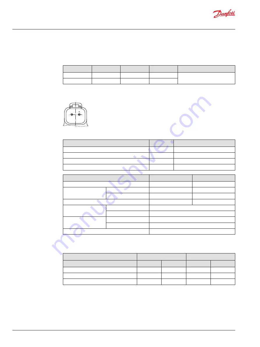
Control Signal Requirements
Control current
Voltage
a
*
b
c
Pin connections
12 V
600 mA
1080 mA
1360 mA
any order
24 V
300 mA
540 mA
680 mA
*
Factory test current, for vehicle movement or application actuation expect higher or lower value.
DEUTSCH connector, 2-pin
1
2
P003 480
Connector ordering data
Description
Quantity
Ordering data
Mating connector
1
DEUTSCH DT06-2S
Wedge lock
1
DEUTSCH W2S
Socket contact (16 and 18 AWG)
2
DEUTSCH 0462-201-16141
Danfoss mating connector kit
1
K29657
Description
12 V
24 V
Maximum current
1800 mA
920 mA
Nominal coil resistance
@ 20 °C [68 °F]
3.66 Ω
14.20 Ω
@ 80 °C [176 °F]
4.52 Ω
17.52 Ω
Inductance
33 mH
140 mH
PWM signal frequency
Range
70 – 200 Hz
Recommended
*
100 Hz
IP Rating
IEC 60 529
IP 67
DIN 40 050, part 9
IP 69K with mating connector
Connector color
Black
*
PWM signal required for optimum control performance.
Pump output flow direction vs. control signal
Shaft rotation
CW
CCW
Coil energized
*
C1
C2
C1
C2
Port A
in
out
out
in
Port B
out
in
in
out
Servo port pressurized
M5
M4
M5
M4
*
For coil location see Installation drawings.
Control Response
MP1 controls are available with optional control passage orifices to assist in matching the rate of
swashplate response to the application requirements (e.g. in the event of electrical failure). The time
required for the pump output flow to change from zero to full flow (acceleration) or full flow to zero
(deceleration) is a net function of spool porting, orifices, and charge pressure. A swashplate response
Service Manual
MP1
Operation
28 |
©
Danfoss | April 2019
AX00000244en-000201


