AK-CT
450A
User
Guide RS8GR602 © Danfoss 2016-10
27
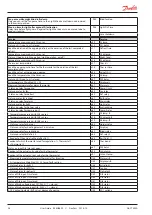
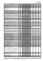
Rail heat control
The rail heat can be controlled in several ways:
0: The function is not used
1: Pulse control is used with a timer function following the day/night operation
(o41 and o42)
2: Pulse control is used with a dew point function. This function requires that a signal
is received about the dew point value. The value is measured by a system manager
and sent to the controller via the data communication.
o85
Railh. mode
Dew point value where the rail heat is minimum
This function is discussed earlier in the manual.
o86
DewP Min lim
Dew point value where the rail heat is maximum
This function is discussed earlier in the manual.
o87
DewP Max lim
Lowest permitted rail heat effect
Here the % part of the effect to be achieved when the dew point value is minimum.
o88
Rail Min ON%
Start of refrigeration when door is open
If the door has been left open, refrigeration must be started after a set time. That time
can be set here.
o89
DoorInjStart
Fan operation for forced closing
If “forced closing” is activated, it will affect the operation of the fan and the defrosting.
Select the desired settings:
0: The fans will stop. Defrosting permitted.
1: The fans will run. Defrosting permitted.
(For 0 and 1: If the “forced closing” signal comes during a defrosting cycle,
or if a new defrosting cycle begins, the fans will follow the setting in d09.)
2: The fans will stop. Defrosting not permitted.
3: The fans will run. Defrosting not permitted.
(For 2 and 3: If the “forced closing” signal interrupts a defrosting cycle
but disappears again within 10 minutes, the defrosting cycle will resume.)
o90
Fan forcedCl
Alternative display
A reading can be displayed by pressing the lower button on the controller. This
reading is set from the factory so that the defrosting stop temperature is displayed.
A different setting will give the following reading:
1: (Defrost stop temperature = factory setting)
2: S6 temperature
o92
Displ menu 2
Display of temperature during normal operation
1: Air temperature. Weighted S3 + S4
2: Product temperature S6
o97
Disp. Ctrl.
Light and night blinds definition
0: Light is switched off and night blinds are open when the main switch is off
1: Light and night blinds are independent of main switch.
o98
Light MS = Off
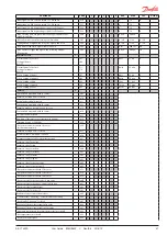
Configuration of alarm relay
The alarm relay will be activated upon an alarm signal from the following groups:
0 - No relay function
1 - High temperature alarms
2 - Low temperature alarms
4 - Sensor error
8 - Digital input enabled for alarm
16 - Defrosting alarms
32 - Miscellaneous
64 - Injection alarms
128 - Disconnected fuse
The groups that are to activate the alarm relay must be set by using a numerical value
which is the sum of the groups that must be activated.
(E.g.: a value of 5 will activate all high temperature alarms and all sensor error.
P41
Al.Rel.Conf.
Digital input signal - DI4. Switch signal. See DI3 above
P55
DI4 config.
Digital input signal - DI5. Switch signal. See DI3 above
P56
DI5 config.
Digital input signal - DI6. Switch signal. See DI3 above
P57
DI6 config.
Digital input signal - DI7. High voltage signal. Functions the same as those
for DI3, but signal is 0 V/230 V. See also the summary on page 12.
P58
DI7 config.
Digital input signal - DI8. High voltage signal. See DI7 above
P59
DI8 config.
Max. opening time for night blind after manual DI activation
The delay time before the night blind automatically goes down again after being
manually opened for product stocking.
P60
BlindOpenTim
Reset settings on ID module
Reset all settings so that the ID module can receive settings from another controller.
P61
ResetID Mem.
Configuration of night blind function
On= night blind function used. Off=night blind function not used.
P64
Blind config

