AK-CT
450A
User
Guide RS8GR602 © Danfoss 2016-10
21
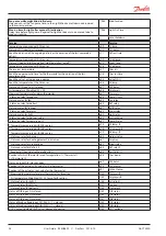
Delay of a DI1 alarm
A cut-out/cut-in input will result in alarm when the time delay has been passed.
The function is defined in o02.
A27
AI.Delay DI1
Delay of a DI2 alarm
A cut-out/cut-in input will result in alarm when the time delay has been passed.
The function is defined in o37
A28
AI.Delay DI2
Signal to the alarm thermostat
Here you have to define the ratio between the sensors which the alarm thermostat
has to use. S3, S4 or a combination of the two.
With setting 0% only S3 is used. With 100% only S4 is used.
(The setting also applies to a possible B section - S3B, S4)
A36
Alarm S4%
Time delay on S6 (product sensor) for pull-down
(long alarm delay)
This time delay is used for start-up, during defrosting, immediately after a defrost and
after an appliance clean.
A change is carried out to standard time delay (A26) when the temperature has
reached below the set upper alarm limit.
The time delay is set in minutes.
A52
PullD del.S6
Alarm delay (short alarm delay on section B air temperature)
A timer function starts if the top or bottom alarm limit is exceeded. The alarm will first
becomes active when the set delay time has been exceeded.
The time delay is set in minutes.
A53
AI.Delay S3B
Reset alarm
EKC error
Compressor
Compressor control
The compressor relay works in conjunction with the thermostat. When the
thermostat calls for refrigeration the compressor relay be operated.
Running times
To prevent irregular operation, values can be set for the time the compressor is to run
once it has been started. And for how long it at least has to be stopped.
The running times are not observed when defrosts start.
Min. ON-time (in minutes)
c01
Min. On time
Min. OFF-time (in minutes)
c02
Min. Off time
Time delay for couplings of two compressors
Settings indicate the time that has to elapse from the first relay cuts in and until
the next relay has to cut in.
c05
Step delay
u58 comp1/LLSV
Here you can read the status of the
compressor relay.
Defrost
Defrost control
The controller contains a timer function that is zeroset after each defrost start.
The timer function will start a defrost if/when the interval time is passed.
The timer function starts when voltage is connected to the controller, but it is
displaced the first time by the setting in d05.
If there is power failure the timer value will be saved and continue from here when
the power returns.
This timer function can be used as a simple way of starting defrosts, but it will always
act as safety defrost if one of the subsequent defrost starts is not received.
The controller also contains a real-time clock. By means of settings of this clock and
times for the required defrost times, defrost can be started at fixed times of the day.
Defrost start can also be accomplished via data communication, via contact signals or
manual start-up.
All starting methods will function in the controller. The different functions have to be
set, so that multiple defrosts are avoided..
Defrost can be performed using electricity, hot gas, naturally or brine.
The actual defrost will be stopped based on time or temperature with a signal from
a temperature sensor.
Defrost method
Here you set whether defrost is to be accomplished with electricity, gas, "air" or brine.
During defrost the defrost relay will be cut in.
d01
Def. method
0 = non. 1 = El. 2 = Gas. 3 = Brine.
4 = Air.
Defrost stop temperature
The defrost is stopped at a given temperature which is measured with a sensor
(the sensor is defined in d10).
The temperature value is set.
d02
Def. Stop Temp


