background image

10 

User 

Guide RS8GR602 © Danfoss 2016-10 

AK-CT 

450A

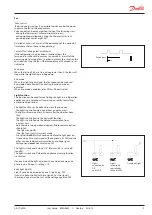
Night blind

Motorised night blind can be controlled automatically from  

the controller. The night blinds will follow the status of the light 

function. When the light is switched on, the night blinds opens 

and when the light is switched off, the night blinds close again. 

When the night blinds are closed, it is possible to open them  

using a pulse signal on the digital input. If this input is activated, 

the night blinds will open and the refrigeration appliance can  

be filled with new products. If the input is activated again,  

the blinds close again.

If the activation is omitted, the blind will close automatically  

when the delay time expires. A setting is used to define whether 

the light is to be on or off when the night blind is up.

When the night blind function is used, the thermostat function 

can control with different weighting between the S3 and S4 

sensors. A weighting during day operation and another when  

the blind is closed.

A night blind is open when the appliance cleaning function  

is activated.

A setting can define that the night blind is open when "r12"  

(Main switch) is set to off (see o98).

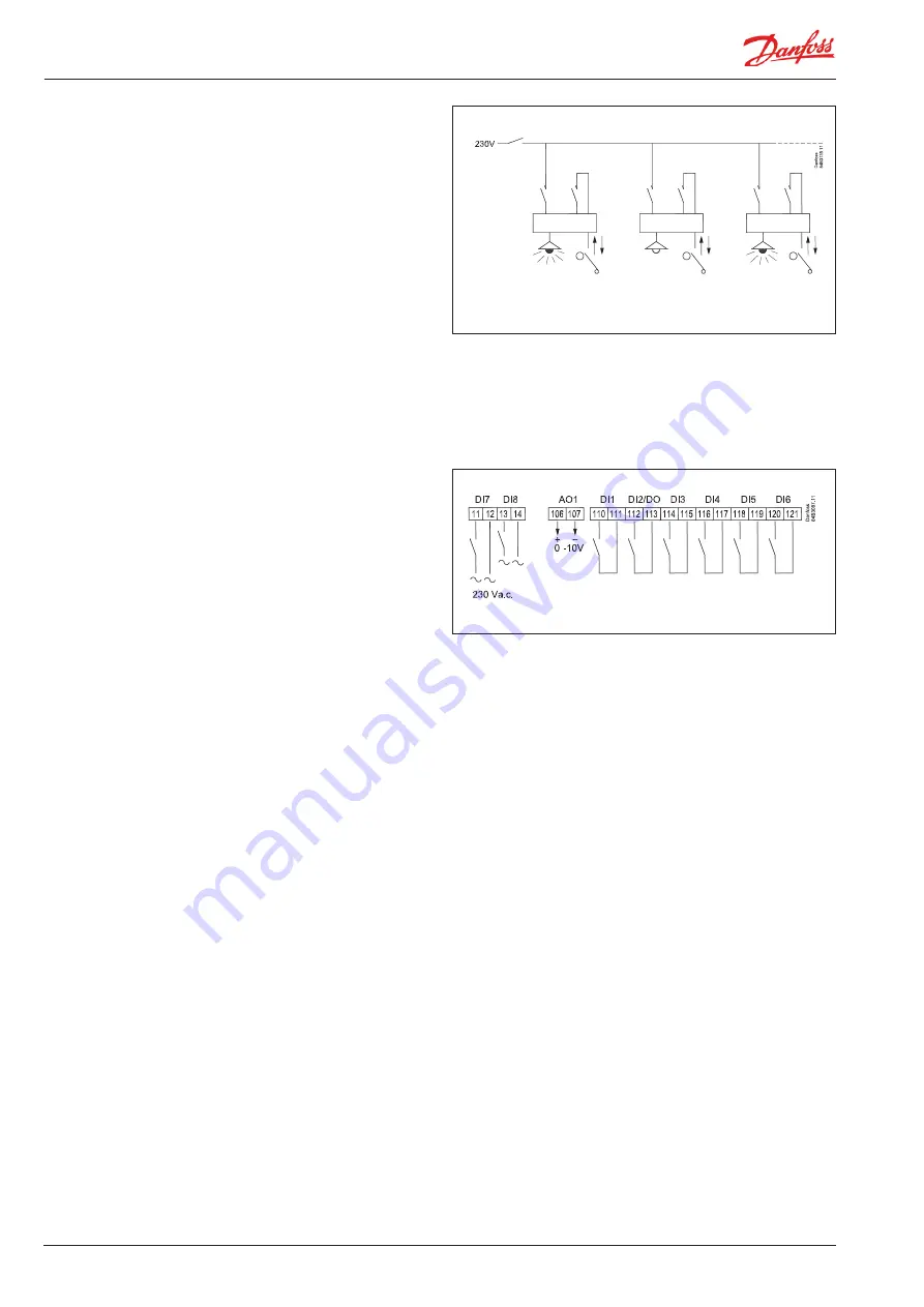
Digital inputs

There are six digital inputs with contact function and two digital 

inputs with high voltage signal. 

They can be used for the following functions:

- Retransmission of contacts position via data communication

- Door contact function with alarm

- Starting or cancelling a defrost cycle

- Main switch - start/stop of cooling

- Night setback

- Thermostat bands switch

- General alarm monitoring

- Case cleaning

- Forced cooling

- Override of night blinds

- Coordinated defrost (DI2 only)

- Forced closing of valve

- Appliance shutdown

- Light, Extra light, Override light

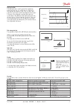
Forced closing

The solenoid valve can be closed with an external signal  

( "Forced closing").

If a defrost cycle is in progress, the forced closing status will not  

be re-established until the defrost is completed.  Otherwise,  

the defrost cycle will be stopped immediately when the signal  

is received.  The function can be defined in o90. The signal can  

be received from the DI3-input or via the data communication. 

During a forced closing the fans can be defined to be stopped  

or in operation.

Door contact

The door contact function can via the digital inputs be defined  

for two different  applications:

Alarm monitoring

The controller monitors the door contact and delivers an alarm 

message if the door has been opened for a longer period than 

the set alarm delay.

Alarm monitoring and stop of refrigeration

When the door is opened the refrigeration is stopped, i.e. the 

injection, the compressor and the fan are stopped and light 

switch on.

 If the door remains open for a longer time than the set restart 

time, refrigeration will be resumed. This will ensure that 

refrigeration is maintained even if the door is left open or  

if the door contact should be defective. If the door remains 

open for a longer period than the set alarm delay an alarm  

will also be triggered.

Содержание ADAP-KOOL AK-CT 200A

Страница 1: ...User guide ADAP KOOL Refrigeration control systems Controller tray for refrigeration appliance control with TEV AK CT 200A AK CT 450A AK CT 450A ...

Страница 2: ...onally placed in the appliance can be used to register the temperature near the required product in a certain place within the appliance The temperature of the evaporator is registered with the S5 sensor which can be used as a defrosting sensor In addition to the output for the solenoid valve type EVR the con troller has 9 relay outputs which are defined by the use selected the individual usage op...

Страница 3: ...stalled by the refrigeration appliance manufacturer such as High relay load Load connection disconnection is controlled by a voltage measurement and a current measurement so that the relay s switch function can operate under optimal conditions The controller can then connect loads of up to 16 A without the use of auxiliary relays Spring clamps All cable connections are made using plugs with spring...

Страница 4: ...control as it can only be used in DX central plant or brine system In principle regulation in this system is the same as described above but is now performed with a PI function This results in reduced fluctuation of the regulated air temperature with stable loads giving a more constant air humidity The function gives a constant temperature regulation with a tem perature value which lies half way b...

Страница 5: ...r the product sensor Appliance cleaning This function makes it easy for the shop s staff to carry out a cleaning of the appliance according to a standard procedure Appliance cleaning is activated via a signal as a rule via a key switch placed on the appliance Appliance cleaning is carried out via three phases 1 at the first activation the refrigeration is stopped but the fans keep on operating in ...

Страница 6: ...ay heating element It is possible to control a heating element in the drip tray for hot gas defrosting When defrosting is commenced the heating element is activated The heating element remains activated until a set time after defrosting has ended by time or temperature Start of defrost A defrost can be started in different ways Interval Defrost is started at fixed time intervals say every eighth h...

Страница 7: ...igeration time has passed a fixed time a defrost will be started Min time between defrosts There is a 2 hours minimum time between defrosts This avoids that planned defrosts in accordance with the weekly schedule are carried out immediately after a defrost on demand has been carried out The time applies from when a Defrost based on refrigeration time has been completed to when a planned defrost is...

Страница 8: ...e top priority during normal regulation But if one of the override functions is activated the Min On time will be disregarded Railheat It is possible to pulse control the power to the rail heat in order to save energy Pulse control can either be controlled according to day night load or dew point Pulse control according to day and night Various ON periods can be set for day and night operation A p...

Страница 9: ...or controlling the light in a refrigeration appliance or in a cold room It can also be used for controlling a motorised night blind The light function can be defined in more than one way The light is controlled via a signal from a door contact The light will remain on for 2 minutes after the door has been shut The light is controlled via the day night function The light is controlled via the data ...

Страница 10: ...ontact function with alarm Starting or cancelling a defrost cycle Main switch start stop of cooling Night setback Thermostat bands switch General alarm monitoring Case cleaning Forced cooling Override of night blinds Coordinated defrost DI2 only Forced closing of valve Appliance shutdown Light Extra light Override light Forced closing The solenoid valve can be closed with an external signal Forced...

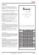
Страница 11: ...The controller contains a number of functions which can be used together with the override function in the master gateway system manager Function via data communication Function in gateway system manager Used parameters in AK CT 450A Start of defrosting Defrost control Time schedule Defrost group Def start Coordinated defrost Defrost control Defrost group HoldAfterDef DefrostState Prevent defrost ...

Страница 12: ...e the functions in the respective settings o02 o37 o84 etc Control of night blinds Night blinds follow the status of the light function when the light is switched on the night blinds are up and when the light is switched off the night blinds are down In addition a digital input provides the option of forced opening of the blinds so that the appliance can be filled with products Heat thermostat The...

Страница 13: ...AK CT 450A User Guide RS8GR602 Danfoss 2016 10 13 o61 1 2 Standard use Standard use with 3 phase defrost ...

Страница 14: ...de RS8GR602 Danfoss 2016 10 AK CT 450A 3 4 Two cooling sections two evaporators Standard Defrost on phase 1 and phase 3 Individual defrost stop with S5 and S5B Two cooling sections two evaporators 3 phase defrost ...

Страница 15: ...AK CT 450A User Guide RS8GR602 Danfoss 2016 10 15 5 6 Two cooling sections one evaporator 3 phase defrost Two cooling sections one evaporator Standard ...

Страница 16: ...he drain valve There is no time delay between stops of hot gas and start of draining Two compressor operation The two compressors must be of the same size On start up after defrosting operational stop etc both compressors are started with a set time shift One compressor starts at half the differential so that an optimum adaptation of compressor capacity takes place for the current load in the appl...

Страница 17: ...ong installation for example could still present problems Electronic controls are no substitute for normal good engineering practice Danfoss will not be responsible for any goods or plant compo nents damaged as a result of the above defects It is the installer s responsibility to check the installation thoroughly and to fit the necessary safety devices Special reference is made to the necessity of...

Страница 18: ...e settings will be saved in both the controller and the module A module with settings will always overwrite the settings in the controller An overwrite will be finished 3 seconds after the controller is turned on The module can be removed from the controller for a short period of time in order to transfer the settings to another corresponding controller Remember to disconnect the voltage to ensure...

Страница 19: ...F r05 Temp unit C 0 F 1 Only C on AKM whatever the setting Correction of signal from S4 Compensation possibility due to long sensor cable r09 Adjust S4 Correction of signal from S3 and S3B Compensation possibility due to long sensor cable r10 Adjust S3 Start stop of refrigeration With this setting refrigeration can be started stopped or a manual override of the outputs can be allowed For manual co...

Страница 20: ...carried out in the Alarm destinations menu via AKM Alarm delay short alarm delay on air temperature If the upper or the lower alarm limit values are exceeded a timer function will commence The alarm will not become active until the set time delay has been passed The time delay is set in minutes A03 Alarm delay Time delay for door alarm The time delay is set in minutes The function is defined for a...

Страница 21: ...Min ON time in minutes c01 Min On time Min OFF time in minutes c02 Min Off time Time delay for couplings of two compressors Settings indicate the time that has to elapse from the first relay cuts in and until the next relay has to cut in c05 Step delay u58 comp1 LLSV Here you can read the status of the compressor relay Defrost Defrost control The controller contains a timer function that is zerose...

Страница 22: ...agg Drip off time Here you set the time that is to elapse from a defrost and until the compressor is to start again The time when water drips off the evaporator d06 DripOff time Delay of fan start after defrost Here you set the time that is to elapse from compressor start after a defrost and until the fan may start again The time when water is tied to the evaporator d07 FanStartDel Fan start tempe...

Страница 23: ...topTemp Pulse operation of fan 0 No pulse operation 1 Pulse operation when the thermostat does not call for refrigeration 2 Pulse operation when the thermostat does not call for refrigeration but only during night operation F05 FanPulseMode Pulse operation period for fan Here the overall pulse time is set The sum of ON to and OFF time F06 Fan cycle ON time for fan Here the part of the period the f...

Страница 24: ...ntroller s functions can be delayed so that overloading of the electricity supply network is avoided Here you can set the time delay o01 DelayOfOutp Digital input signal DI1 The controller has a digital input 1 which can be used for one of the following functions Off The input is not used 1 Status display of a contact function 2 Door function When the input is open it signals that the door is open...

Страница 25: ... can be used for one of the following functions Off The input is not used 1 Status display of a contact function 2 Door function When the input is open it signals that the door is open The refrig eration and the fans are stopped and light turn on When the time setting in A04 has passed an alarm will be issued The cooling is restarted when the time in o89 has passed 3 Door alarm When the input is o...

Страница 26: ...survey of applications This menu can only be set when regulation is stopped i e r12 is set to 0 o61 Appl Mode Access code 2 Access to adjustments There is access to adjustments of values but not to configuration settings If the settings in the controller are to be protected with an access code you can set a numerical value between 0 and 100 If not you can cancel the function with setting 0 If the ...

Страница 27: ... is set from the factory so that the defrosting stop temperature is displayed A different setting will give the following reading 1 Defrost stop temperature factory setting 2 S6 temperature o92 Displ menu 2 Display of temperature during normal operation 1 Air temperature Weighted S3 S4 2 Product temperature S6 o97 Disp Ctrl Light and night blinds definition 0 Light is switched off and night blinds...

Страница 28: ...lay for railheat u61 Railh relay Status on relay for alarm u62 Alarm relay Status on relay for light u63 Light relay Status on relay for hot gas valve u64 SuctionValve Status on relay for compressor 2 u67 Comp2 relay Temperature measured with S5B sensor u75 S5 temp B Temperature measured with S3B sensor u76 S3 air temp B Temperature measured with S6B sensor u79 S6 temp B Status on relay for hot ga...

Страница 29: ...sage of DI2 signal 0 see status in u37 1 output for coordinated defrost U54 DI2 In Out Status of relay for drain valve 1 on U55 Drain valve ON indicates controller error EKC error Dewpoint value received from system unit Dew point Not all will be displayed Only the function belonging to the selection application is displayed ...

Страница 30: ...ess S14 14 Defrost sequence Fan delay water attaches to the evaporator S15 15 Forced closing Refrigeration stopped due to stopped injection function S16 16 Door is open DI input is open S17 17 Melt function in progress Refrigeration is interrupted S18 18 Modulating thermostat control S19 19 Emergency cooling due to sensor error S20 20 Normal control S23 23 Manual control of outputs S25 25 Case cle...

Страница 31: ...ut A70 High temp S3B High temperature alarm B section 1 A71 Low temp S3B Low temperature alarm B section 2 A72 High temp S6B High temperature alarm B section 1 A73 Low temp S6B Low temperature alarm B section 2 E1 Ctrl error Faults in the controller 32 E6 RTC error Check clock 32 E25 S3 error Error on S3 sensor 4 E26 S4 error Error on S4 sensor 4 E27 S5 error Error on S5 sensor 4 E28 S6 error Erro...

Страница 32: ...ed the value save the new value by once more pushing the middle button Examples Set menu 1 Push the upper button until configuration access cFg is shown 2 Push the upper or the lower button and find that parameter you want to change 3 Push the middle button to enter the group 4 Push the upper or the lower button and find that parameter you want to change 5 Push the middle button until the paramete...

Страница 33: ...k 3 Meat fish 4 Frost 5 Ice Temperature SP 8 C 0 C 2 C 20 C 24 C Max temp setting r02 10 C 4 C 2 C 16 C 20 C Min temp setting r03 4 C 4 C 6 C 24 C 28 C Upper alarm limit A13 14 C 8 C 8 C 15 C 15 C Lower alarm limit A14 0 C 5 C 5 C 30 C 30 C Product type Menu overview Get a good start With the following procedure you can start regulation very quickly 1 Basic settings entered by appliance manufactur...

Страница 34: ...tting after 240 min the heating function is deactivated r63 1 1 1 1 1 1 1 1 0 min 240 min 240 Product type use settings listed in table r89 1 1 1 1 1 1 1 1 0 5 0 Alarms A Delay for temperature alarm A03 1 1 1 1 1 1 1 1 0 min 240 min 30 Delay for door alarm A04 1 1 1 1 1 1 1 1 0 min 240 min 60 Delay for temperature alarm after defrost A12 1 1 1 1 1 1 1 1 0 min 240 min 90 High alarm limit for thermo...

Страница 35: ...1 1 1 0 off 1 on 1 on Electrical current value at which relay cuts out 0 not used Recommended setting measured consumption 25 L31 1 1 1 1 1 1 1 1 0 4A 16 A 16 Same for relays 2 to 8 L32 L38 1 1 1 1 1 1 1 1 0 4A 16 A 16 Current measured voltage in phase L1 L51 1 1 1 1 1 1 1 1 V Current measured voltage in phase L2 L52 1 1 1 1 1 1 1 1 V Current measured voltage in phase L3 L53 1 1 1 1 1 1 1 1 V Alar...

Страница 36: ... 4 defrost start pulse signal 5 ext main switch 6 night operation 7 thermostat band changeover activate r21 8 Not used 9 Not used 10 case cleaning pulse signal 11 forced cooling at hot gas defrost 12 night cover 13 Not used 14 Refrigeration stopped forced closing 15 appliance shutdown 16 light 17 extra light 18 cancel defrost 19 override light o84 1 1 1 1 1 1 1 1 0 19 0 Rail heat control 0 not use...

Страница 37: ... 1 Status on night operation on or off 1 on u13 1 1 1 1 1 1 1 1 Temperature measured with S4 sensor u16 1 1 1 1 1 1 1 1 Thermostat temperature u17 1 1 1 1 1 1 1 1 Run time of thermostat cooling time in minutes u18 1 1 1 1 1 1 1 1 Opening degree of EVR valve u23 1 1 1 1 1 1 1 1 Temperature measured with S6 sensor product temperature u36 1 1 1 1 1 1 1 1 Status on DI2 input on 1 closed u37 1 1 1 1 1 ...

Страница 38: ... u37 1 output for coordinated defrost U54 1 1 1 1 1 1 1 1 Status of relay to drain valve 1 drawn U55 1 Continued Code 1 2 3 4 5 6 7 8 Min Max Fac Actual Can only be set when regulation is stopped r12 0 Can be controlled manually but only when r12 1 With access code 2 the access to these menus will be limited Factory setting Follow these steps if you need to return to the factory set values Connect...

Страница 39: ...ontrolling thermostatic controlled expansion valve 084B0042 1 pcs 084B0072 60 pcs EKA 163B External display with plug for direct connection 084B8574 EKA 164B External display with operation buttons and plug for direct connections 084B8575 Cable with plug for display unit 24 pcs 0 3 m 2 m 3 m 6 m 9 m 084B7500 084B7179 084B7099 084B7097 084B7630 Console for mounting display on wall 084B8584 EKA 175 ...

Страница 40: ...0 10 A 15 min 1A Display 2 plugs for connecting external display External display EKA 163B or 164B Digital inputs DI1 DI2 DI3 DI4 DI5 DI6 Signal from contact functions Requirements to contacts None Cable length must be max 15 m Use auxiliary relays when the cable is longer Digital inputs DI7 DI8 230 V a c On DI 80 V a c Off DI 24 V a c Electrical con nection cable Max 2 5 mm2 Relays DO1 DO8 Max 16...

Отзывы: