background image

Troubleshooting

20

Low-Frequency Driver (A-1903)

Tools Required: 

9/16 wrench, #2 Phillips 

screwdriver, 3/16 Allen wrench, silicone 

1� 

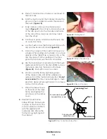
Remove the front mesh assembly (45 lb 

[20 kg]): 

a� 

Remove 8 bolts (4 top, 4 bottom) with 

9/16 wrench. 

b� 

Pull the mesh assembly off. 

2� 

Remove suspected bad driver(s): 

a� 

Remove 8 screws with 3/16 Allen wrench. 

b� 

Pull off driver, taking note of positive and negative wire location. 

c� 

Test the driver(s) by following 

Driver Troubleshooting (p�17)

d� 

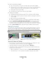
If bad, remove driver (

Figure 30

). 

3� 

Install replacement driver: 

a� 

Reconnect wires, making sure positive and negative go to correct terminals. 

Apply silicone to terminals. 

b� 

Align driver with screw holes. 

c� 

Fasten 8 screws with 3/16 Allen wrench. 

4� 

Reinstall the front mesh assembly. 

5� 

Test the system to verify it is operating correctly per 

System Testing (p�17)

Amplifier Troubleshooting and Replacement

Tools Required: 

#2 Phillips screwdriver, flathead screwdriver 

1� 

Open the control enclosure (

Figure 11

). Note that it may require a key to access. 

2� 

Locate the defective amplifier: 

a� 

Refer to 

System Testing (p�17)

 for basic amplifier troubleshooting, or refer 


to the 

Sportsound Amplifier Field Guide (DD3318172)

, available online at  

www.daktronics.com/manuals

, for more detailed troubleshooting procedures. 

b� 

Once it has been determined that there is a defective amplifier, contact 

Daktronics to order a replacement. 

3� 

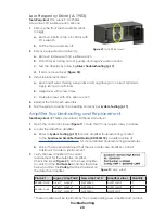
Verify the new amplifier is the correct 

replacement for the defective amplifier. 


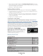
Check the label (

Figure 31

) on the new amplifier 

to verify that the 

Part Number

 matches the table 

below and that the 

Config

 matches the label on 

the defective amplifier. 

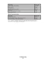
Product

Legacy Amp Part # New Amp Part #

Amplifier Label

Quantity

500HD-SL/SR

A-2611*, A-3636*

A-3922465

AMP1 LMHF

1

500HD-Dual

A-2611*, A-3636*

A-3922465

AMP1 LMHF

1

A-2216*, A-2538*

A-3922601

AMP2 MHF

1

* These amplifiers will be replaced by the corresponding new amplifier part number. 

Figure 30: 

A-1903 Removal

Figure 31: 

Amp Label

Содержание SPORTSOUND 500HD

Страница 1: ...201 Daktronics Drive Brookings SD 57006 5128 www daktronics com support 800 325 8766 SPORTSOUND 500HD AUDIO SYSTEM INSTALLATION MANUAL P1561 DD1798473 Rev 13 30 July 2021 ...

Страница 2: ...he limits for a Class A digital device pursuant to part 15 of the FCC Rules These limits are designed to provide reasonable protection against harmful interference when the equipment is operated in a commercial environment This equipment generates uses and can radiate radio frequency energy and if not installed and used in accordance with the instruction manual may cause harmful interference to ra...

Страница 3: ...net 6 Aim the Speakers 6 Mounting the Control Enclosure 7 4 Electrical Installation 8 Power Signal Connections 8 Power IN 9 Signal IN Fiber 9 Signal IN Analog Only 9 Speaker OUT 9 Grounding 10 Lightning Protection 10 Fiber Conversion Box Connections 10 5 Maintenance 12 Grille Maintenance and Cleaning 12 Grille Mesh Replacement 12 Control Enclosure Maintenance 14 Filters 14 Fan 14 Thermostat 14 6 T...

Страница 4: ...ut Output Expander 22 Typical Component Settings 22 Verifying Network Activity 23 Checking for Input Signal 23 Checking for Output Signal 23 Replacement Parts 23 Sound Cabinet 23 Control Enclosure 23 Fiber Conversion Box 24 7 Daktronics Exchange and Repair Return Programs 25 Exchange Program 25 Repair Return Program 26 Daktronics Warranty Limitation of Liability 26 A Reference Drawings 27 B Supple...

Страница 5: ...ipment or allow it to get wet Always turn off and or unplug the control equipment when it is not in use This keeps equipment protected from power spikes and lightning Inspect equipment for shipping damage such as rattles and dents and verify that all equipment is included as itemized on the packing slip Immediately report any problems to Daktronics save all packing materials if exchange is necessa...

Страница 6: ...act a Daktronics sales coordinator or project manager Daktronics Nomenclature Most components have a white label that lists the part number Figure 2 Part numbers will also appear on certain drawings If a component is not found in the Replacement Parts p 23 use the label to order a replacement Refer to Section 7 Daktronics Exchange and Repair Return Programs p 25 if replacing or repairing any compo...

Страница 7: ...e of the cabinet consists of a woven flame resistant acoustical mesh The mesh can be printed in a variety of colors to display advertising sponsors or logo designs The printable area is 2 9 838 mm high by 8 0 2438 mm wide Drivers The number of drivers also known as speakers will vary based on whether the cabinet is a dual 500HD D or single sided 500HD SL SR model Three different types of drivers a...

Страница 8: ... goes out to the control enclosure The box is typically permanently wall mounted near the source equipment location The fiber conversion box includes an analog backup signal This provides a redundant safety in case the fiber link to the sound cabinet is lost To go into analog backup mode simply turn the switch to the ANALOG position Refer to Fiber Conversion Box Connections p 10 for more informati...

Страница 9: ...d on shop drawings Daktronics also assumes no liability for system damage or injury resulting from incorrect setup or lifting methods performed by non Daktronics employees Cabinet Installation Mechanical installation consists of lifting and mounting the Sportsound 500HD cabinet onto an existing support structure Lift the Cabinet The Sportsound 500HD cabinet may be shipped with two shipping bracket...

Страница 10: ...stallers remove the eyebolts use 1 2 bolts to plug the holes Mount the Cabinet Reference Drawings SS500HD Mounting w Stringer Mounted Displays DWG 992093 Engineering Specification Sportsound 500HD DWG 969776 Side Panel Mounting Details w SS500HD DWG 992088 SS500HD Mounting w Pole Clamp Displays DWG 982267 Single Column Install Specs SS500HD DWG 1005534 The sound cabinet will be mounted atop a fram...

Страница 11: ...e Figure 5 mounts toward the base of the display structure The enclosure typically mounts on the backside of the support column s within 50 15 2 m of the sound cabinet Refer to the drawings listed under Mount the Cabinet p 6 for suggested control enclosure mounting locations Attach horizontal Unistrut pieces to the top and bottom rear flanges of the control enclosure with provided 5 16 hardware th...

Страница 12: ... 230VAC DWG 1115896 System Riser 500HD Copper Signal Only DWG 4137275 DWG 980598 in Appendix A details power and signal connections between the fiber box control enclosure and sound cabinet of the Sportsound 500HD sound system For installations without a fiber box refer instead to DWG 4137275 Refer to Figure 11 for component and connection locations within the control enclosure and DWG 1115742 DWG...

Страница 13: ...y Route 1 pair 22 AWG cable part W 1615 in conduit from the XLR junction box location to the control enclosure and terminate to TRX1 For XLR junction box termination refer to Detail C of DWG 4137275 for TRX1 termination refer to Detail D Speaker OUT IMPORTANT Improper wiring will result in damage to the internal circuitry of the product and pose a potential fire hazard 1 Open the far right rear ac...

Страница 14: ...g damage In order for this device to provide protection the power must be disconnected when the system is not in use Fiber Conversion Box Connections Reference Drawings System Riser 500HD DWG 980598 Audio Sportsound Fiber Box Schematic DWG 1095894 IMPORTANT NOTES The fiber box shall not be exposed to dripping or splashing and no objects filled with liquid shall be placed on the fiber box The fiber...

Страница 15: ...up SWT2 To Control Enclosure Fiber Splice Point FPP1 To Control Enclosure Power Supply PWS1 A 2238 Media Converter FCC2 A 2580 Analog to Digital Converter ADC1 A 2898 Figure 15 Internal Fiber Conversion Box Connections Components Cover Open ...

Страница 16: ...ovable aluminum frame that secures the grille mesh This frame is attached to the sound cabinet with a total of eight 8 3 8 hardware sets with four 4 sets at both the top and bottom of the frame a Carefully remove all mounting hardware and safely lower mesh frame to the ground Set the frame on a level surface large enough so that the weight is supported by the aluminum frame and not on the mesh b L...

Страница 17: ...to place g Use the tensioning tool provided with the mesh replacement kit part 0A 1561 0028 to drive the tension clips into the tension channels Figure 21 Start with one or two clicks h Work around the frame tightening down all the tension clips until all the wrinkles are removed and the mesh is properly taut Do not over tension This may cause damage to mesh graphics Apply just enough tension to a...

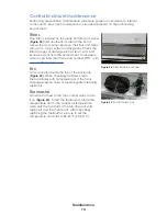
Страница 18: ...nment If necessary order a new filter Hoffman part number WFF1 visit www hoffmanonline com Fan A fan is located inside the top of the enclosure Figure 23 When checking the filters clean the fan blades with compressed air If the fan is making excessive noise or squealing after cleaning replace it Thermostat A thermostat next to the fan controls when to turn it on Figure 23 To test the thermostat ro...

Страница 19: ...conversion box is unplugged from wall outlet or cable to audio control rack Plug in fiber conversion box power signal Analog signal out of the mixer is not being correctly converted to a digital signal Set the fiber box ANALOG BACKUP switch Figure 35 to ANALOG and see if problem goes away No fiber connection to cabinet fiber link down Verify the Port 1 100M LED on the media converter is solid gree...

Страница 20: ...Bring source level down below clip Bad driver or amplifier Perform a system check via Monitor Application Refer to System Testing p 17 Intermittent audio from audio cabinet Bad fiber connection Set the fiber box ANALOG BACKUP switch Figure 35 to ANALOG and see if problem goes away Amplifier modules are over driven into protect mode Reduce source output level Bad amplifier module Open CobraNet Disc...

Страница 21: ...stem click the Start Monitoring button 2 Click the Standby Protect button next to each channel to mute them 3 After muting every channel un mute one channel at a time and listen for audio 4 Un mute all channels and stop all source audio from the control rack 5 Click the Test Tone button for AMP1 and compare the Impedance value in ohms Ω to the reference ranges shown beneath the Channel 6 Repeat St...

Страница 22: ... for any rubbing or stuck coils If the driver checks out fine further troubleshooting of the system is required Note Daktronics speaker assemblies have drivers wired in parallel Use the following chart when measuring the DC resistance of a harness Refer to Figure 26 for harness connector pinout Be sure to disconnect any field terminated wires from the speaker cable terminal block located in the lo...

Страница 23: ...terminals 5 Reinstall rear access door 6 Test the system to verify it is operating correctly per System Testing p 17 Mid Frequency Driver A 2305 Tools Required flathead screwdriver 7 16 wrench 2 silicone 1 Remove the rear access door on the side of the cabinet being serviced using the flathead screwdriver 2 Identify bad driver s by following Driver Troubleshooting p 17 3 Remove bad driver s a Disc...

Страница 24: ...uired 2 Phillips screwdriver flathead screwdriver 1 Open the control enclosure Figure 11 Note that it may require a key to access 2 Locate the defective amplifier a Refer to System Testing p 17 for basic amplifier troubleshooting or refer to the Sportsound Amplifier Field Guide DD3318172 available online at www daktronics com manuals for more detailed troubleshooting procedures b Once it has been ...

Страница 25: ...present should have the firmware verified and updated to the most current version available 7 Refer to System Testing p 17 to verify replacement amplifier is working correctly Media Converters In standard audio systems there are two media converter network switches one in the fiber box and one in the control enclosure that transfer digital audio signal Looking at the connections and LED indicators...

Страница 26: ...rnet jack also has an LED that will light green when a cable to other equipment is connected Refer to Figure 33 2 If these LEDs are not lighting Check Ethernet cable connections Verify connection on opposite end of Cat5e cable Connect known working cable and equipment such as a diagnostic laptop If still not lighting replace the switch Input Output Expander The fiber box if included in the system ...

Страница 27: ... the AC Voltage with a digital multi meter placed between the positive and negative terminals of the male XLR connector If the level is above or below the listed range adjust it using the mixer s channel and master faders Next measure the AC Voltage at the input of the terminal block between the positive and negative terminals Figure 34 2 If it reads the same the device is getting proper signal if...

Страница 28: ... 1247 Transformer Audio Input 1 Channel T 1130 RFI Line Filter 20 Amp Z 1007 Fiber Conversion Box Description Part Number 24 VDC Power Supply A 2238 Industrial Media Converter Ethernet Switch 5 Port A 2580 Converter Analog to Digital with CobraNet A 2898 Refer to Section 7 Daktronics Exchange and Repair Return Programs p 25 for information on exchanging or returning parts ...

Страница 29: ...mer ID Number ______________________________________________________ To participate in the Exchange Program follow these steps 1 Call Daktronics Customer Service United States Canada 1 800 DAK TRON 325 8766 Outside the U S Canada 1 605 275 1040 2 When the new exchange part is received mail the old part to Daktronics If the replacement part fixes the problem send in the problem part being replaced ...

Страница 30: ...prevent damage during shipment Electronic components such as printed circuit boards should be placed in an antistatic bag before boxing Daktronics does not recommend using packing peanuts when shipping 4 Enclose name address phone number the case number a clear description of symptoms 5 Ship to Daktronics Customer Service Case 201 Daktronics Drive Dock E Brookings SD 57006 Daktronics Warranty Limi...

Страница 31: ...io Notes DWG 985713 Side Panel Mounting Details w SS500HD DWG 992088 SS500HD Mounting w Stringer Mounted Displays DWG 992093 Single Column Install Specs SS500HD DWG 1005534 Audio Sportsound Fiber Box Schematic DWG 1095894 Mid High Speaker Adjustment Chart 500HD DWG 1108053 Schematic Control Enclosure 500HD Dual 120VAC DWG 1115742 Schematic Control Enclosure 500HD Single 120VAC DWG 1115872 Schemati...

Страница 32: ...This page intentionally left blank ...

Страница 33: ...ENERAL NOTES 2 1 ALL DIMENSIONS ARE IN FEET AND INCHES 2 2 REFER TO INSTALLATION AND MAINTENANCE MANUAL FOR COMPLETE INSTALLATION INSTRUCTIONS 3 0 SOUND CABINET NOTES 3 1 DAKTRONICS SOUND CABINET IS STEEL CONSTRUCTED SKELETON WITH ALUMINUM PANELING FASTENED TO ITS EXTERIOR 3 2 LIFTING POINTS ARE PROVIDED BY DAKTRONICS WHEN LIFTING USE 45 OR GREATER FROM THE HORIZON CABLE SYSTEM 3 3 PAINT COLOR SPE...

Страница 34: ...RACK ANNOUNCER LOCATION DETAILS N R XB DAK 12 34 56 78 910 GND RED BLK ANALOG BACKUP FROM JB1 THESE ARE 12AWG WIRES 1 AMP1 LF WHT A310 2 AMP1 LF BLK A310 3 AMP1 MF RED A311 4 AMP1 MF BLK A311 5 AMP1 HF BLU A312 FIBER CONVERSION BOX AMP CONTROL ENCLOSURE HOT LEG W 2317 W 1489 W 1615 W 1560 W 2217 3 3 1 4 4 2 NOTE ROUTE ANALOG BACKUP WIRE AS SHOWN W 1615 0A 1340 0327 MAXIMUM WATTS AMPERES PER LINE S...

Страница 35: ...14 0 HSS4X4X3 16 HSS4X4X3 16 HSS4X4X3 16 HSS4X4X3 16 HSS4X4X3 16 HSS4X4X3 16 HSS4X4X3 16 HSS4X4X3 16 HSS4X4X3 16 HSS4X4X3 16 HSS5X5X3 16 HSS5X5X3 16 HSS4X4X3 16 HSS5X5X3 16 HSS5X5X3 16 HSS5X5X3 16 HSS4X4X3 16 HSS5X5X3 16 HSS5X5X3 16 HSS5X5X3 16 HSS4X4X3 16 HSS4X4X3 16 HSS5X5X3 16 HSS5X5X3 16 HSS4X4X3 16 HSS4X4X3 16 HSS5X5X3 16 HSS5X5X3 16 HSS4X4X3 16 HSS4X4X3 16 HSS5X5X3 16 HSS6X6X3 16 TABLE 1 DIS...

Страница 36: ... INC THE CONCEPTS EXPRESSED AND DETAILS SHOWN ON THIS DRAWING ARE CONFIDENTIAL AND PROPRIETARY DO NOT REPRODUCE BY ANY MEANS WITHOUT THE EXPRESSED WRITTEN CONSENT OF DAKTRONICS INC COPYRIGHT 2011 DAKTRONICS INC BROOKINGS SD 57006 DO NOT SCALE DRAWING PROJ DAKTRONICS AUDIO SYSTEMS TITLE MESH LAYOUT SS500HD DESIGN KSCHNABEL DRAWN KSCHNABEL DATE 10 JUN 13 SCALE 1 12 SHEET REV JOB NO FUNC TYPE SIZE 98...

Страница 37: ......

Страница 38: ...E 45 OR GREATER FROM THE HORIZON CABLE SYSTEM ALIGN LIFT EYES WITH CABLES 3 3 REMOVE SHIPPING BRACKETS FROM TOP OF CABINET 3 4 PAINT COLOR SPEAKER CABINET COLOR POWDER COAT BLACK 4 0 STRUCTURAL NOTES 4 1 FABRICATION AND ERECTION SHALL CONFORM TO THE LATEST EDITION OF AISC SPECIFCATIONS 4 2 ALL WELDING SHOP AND FIELD SHALL BE PERFORMED IN ACCORDANCE WITH AWS D1 1 LATEST EDITION SPECIFICATIONS BY A ...

Страница 39: ...N MUST BE CERTIFIED BY A PROFESSIONAL ENGINEER LICENSED IN THE STATE OF THE INSTALLATION BEFORE THEY CAN BE USED FOR FABRICATION OR ERECTION 2 0 GENERAL NOTES 2 1 ALL DIMENSIONS ARE IN FEET AND INCHES 2 2 REFER TO INSTALLATION AND MAINTENANCE MANUAL FOR COMPLETE INSTALLATION INSTRUCTIONS 3 0 SOUND CABINET NOTES 3 1 DAKTRONICS SOUND CABINET IS STEEL CONSTRUCTED SKELETON WITH ALUMINUM PANELING FASTE...

Страница 40: ...0HD SYSTEM RISER 2 0 WELDING NOTES 2 1 ALL WELDING SHOP AND FIELD SHALL BE PERFORMED IN ACCORDANCE WITH AWS D1 1 LATEST EDITIONS WELDERS SHALL BE QUALIFIED IN ACCORDANCE WITH D1 1 LATEST EDITIONS 2 2 MINIMUM ELECTRODE STRENGTH IS 70 KSI 2 3 DIMENSIONS AND SQUARENESS IS CRITICAL WITH TOLERANCE OF 1 16 2 4 MAXIMUM ALLOWABLE GAP BETWEEN MATING COMPONENTS OF 1 16 2 5 WELD ALL AROUND UNLESS OTHERWISE N...

Страница 41: ...UMPER WIRES L W 1054 22AWG BLACK JUMPER WIRES M N W 1615 22AWG AUDIO 1 PAIR W 1080 14AWG GREEN YELLOW W 1080 14AWG GREEN YELLOW DATE REV BY 02 24 JUN 13 CJB UPDATED WIRING WIRE C N INCLUDED IN 0A 1534 0077 THE CONCEPTS EXPRESSED AND DETAILS SHOWN ON THIS DRAWING ARE CONFIDENTIAL AND PROPRIETARY DO NOT REPRODUCE BY ANY MEANS WITHOUT THE EXPRESS WRITTEN CONSENT OF DAKTRONICS INC OR ITS WHOLLY OWNED ...

Страница 42: ...This page intentionally left blank ...

Страница 43: ...FOR EACH HORN HORNS ARE DESIGNED TO CROSSFIRE TO COVER BOTH SIDES OF VENUE 0 0 10 0 20 0 30 0 40 0 50 0 60 0 70 0 80 0 10 0 20 0 30 0 40 0 50 0 60 0 70 0 80 0 0 0 15 0 30 0 45 0 60 0 75 0 90 0 105 0 120 0 135 0 150 0 180 0 15 0 30 0 45 0 60 0 75 0 90 0 105 0 120 0 135 0 150 0 180 0 360 0 SPEAKER AIMING CHART DISTANCE A ANGLE X VALUE X IS IN DEGREES 250 30 240 30 30 220 30 30 30 210 30 30 30 30 200...

Страница 44: ...RED BLK BLU BLK ORG GRN BLK WHT BLK RED BLK BLU BLK GRN BLK A 3482091 MID FREQUENCY ASSEMBLY CONNECTION TERMINALS RED RED BLK BLU SPK5 E A 0A 1561 0019 HARNESS CONTROL CABINET GROUND BLK V RED M RED BLK W 1489 6 STRAND 50uM DX FIBER FIBER COLORS FROM FPP2 1 BLU 2 ORG 3 GRN 4 BRN 5 SLT 6 WHT DES C DES 1 2 4 5 6 TX RX FPP2 A A E E E F F 0M 788412 P 1197 6 A204 N2 L2 A200 PWS2_GND TERM_BLK TBL1 GND T...

Страница 45: ...247 THE CONCEPTS EXPRESSED AND DETAILS SHOWN ON THIS DRAWING ARE CONFIDENTIAL AND PROPRIETARY DO NOT REPRODUCE BY ANY MEANS WITHOUT THE EXPRESS WRITTEN CONSENT OF DAKTRONICS INC OR ITS WHOLLY OWNED SUBSIDIARIES COPYRIGHT 2016 DAKTRONICS INC USA THIRD ANGLE PROJECTION BH REV TITLE PROJECT INCHES MILLIMETERS DESIGN SCALE DIM UNITS DATE SHEET DO NOT SCALE DRAWING FUNC TYPE SIZE DRAWN JOB NO SPORTSOUN...

Страница 46: ...1694 A204 RED BLK L K RED BLK W 1489 6 STRAND 50uM DX FIBER FIBER COLORS FROM FPP2 1 BLU 2 ORG 3 GRN 4 BRN 5 SLT 6 WHT DES C DES 1 2 3 4 5 6 TX RX FPP2 A A E E E F F 0M 788412 P 1197 6 A204 DES A20 DES N L1 A200 PWS2_GND TERM_BLK TBL1 GND TB 1186 GND_BAR TB 1037 TO CABINET GROUND LUG LOCATED TOP RIGHT OF CABINET M ELECTRICIANS CONNECTIONS 2 CONDUCTS GND 230VAC 20A 12AWG A205 B P G J Q C W 1080 REF...

Страница 47: ...TROL CABINET GROUND 0A 1561 0016 HARNESS SP 2 AMPLIFIER P 0A 1340 0081 2 5 XLR M TO PIGTAIL Q W 1917 2 M XLR TO F XLR RED BLK SHLD PANEL MOUNT LED V V LED1 DS 1694 A204 RED BLK L K RED BLK W 1489 6 STRAND 50uM DX FIBER FIBER COLORS FROM FPP2 1 BLU 2 ORG 3 GRN 4 BRN 5 SLT 6 WHT DES C DES 1 2 3 4 5 6 TX RX FPP2 A A E E E F F 0M 788412 P 1197 6 A204 DES A20 DES N L1 A200 PWS2_GND TERM_BLK TBL1 GND TB...

Страница 48: ... AS POSSIBLE 6 WHEN CONTROL ENCLOSURE IS ADJUSTED TO FINAL DESIRED POSITION TIGHTEN BOLTS FIRMLY NOTE CONTROL ENCLOSURE MUST BE MOUNTED WITHIN 50 OF THE 500HD SOUND SYSTEM FOR SIGNAL CABLE TO REACH REFERENCE PACKET 0A 1561 0049 CRITICAL DO NOT USE ANY LUBRICANT ON ANY MOUNTING HARDWARE OR WARRANTY WILL BE VOIDED TOP VIEW CTRL ENCL ATTACHMENT SCALE 1 6 BACK OF CONTROL ENCLOSURE I BEAM CLAMP 4 SPRIN...

Страница 49: ...NICS OTHERS JB1 JUNCTION BOX W FEMALE 3 PIN XLR EC 3339265 DAKTRONICS OTHERS JB2 CONTROL ENCLOSURE SINGLE 120V 0A 1561 0008 DAKTRONICS OTHERS WIRE TAGS DETAILS FOR WIRE TAGS DWG 985713 DAKTRONICS GROUND TB 1058 6 AMP1 HF BLK A312 7 AMP2 MF ORG A313 8 AMP2 MF BLK A313 9 AMP2 HF GRN A314 10 AMP2 HF BLK A314 DETAIL D T 1130 ANALOG BACKUP TRANSFORMER GND RED BLK THIS SIDE FACTORY TERMINATED AMP ONLY P...

Страница 50: ...This page intentionally left blank ...

Страница 51: ... When viewing a digital copy of this manual from www daktronics com manuals click on the appropriate manufacturer link below to view a component s manual If the link is broken visit the manufacturer s website or perform a web search for the component model number Component Model Number Manufacturer Manual s Media Converter Ethernet Switch EDS 205A M ST Moxa www moxa com Installation Guide Analog t...

Страница 52: ...This page intentionally left blank ...

Страница 53: ...Daktronics Warranty Limitation of Liability 49 C Daktronics Warranty Limitation of Liability This section includes the Daktronics Warranty Limitation of Liability statement SL 02374 ...

Страница 54: ...This page intentionally left blank ...

Страница 55: ...ty per Incoterms 2020 otherwise End User shall pay transportation charges to return the Equipment back to the End User and such Equipment shall be shipped Ex Works Daktronics designated facility per Incoterms 2020 All returns must be pre approved by Daktronics before shipment Daktronics shall not be obligated to pay freight for any unapproved return End User shall pay any upgraded or expedited tra...

Страница 56: ... Daktronics or M paint or refinishing the Equipment or furnishing material for this purpose 3 Limitation of Liability A Daktronics shall be under no obligation to furnish continued service under this Warranty if alterations are made to the Equipment without the prior written approval of Daktronics B It is specifically agreed that the price of the Equipment is based upon the following limitation of...

Страница 57: ...ration of this warranty Alternatively an Extended Service Agreement may be purchased in conjunction with this Warranty for extended additional services For further information contact Daktronics Customer Service at 1 800 DAKTRONics 1 800 325 8766 Additional Terms applicable to sales outside of the United States The following additional terms apply only where the installation site of the Equipment ...

Страница 58: ...This page intentionally left blank ...

Отзывы: