Troubleshooting
17
Indicator Lights
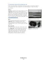
Control Enclosure
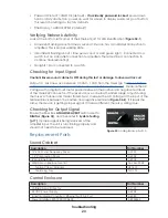
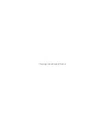
There is a green LED power indicator on the
bottom of the control enclosure (
This indicates whether there is power feeding
the control enclosure properly. The indicator
stays lit when there is power; otherwise, it will
be off.
Audio Control Rack
Refer to the troubleshooting section of a specific audio control rack manual for more
information about the indicator lights that show signal output to the audio cabinet.
Fiber Conversion Box
Within the fiber conversion box, if included, indicator lights on the equipment help verify
proper connection with the sound cabinet. Refer to
and
System Testing
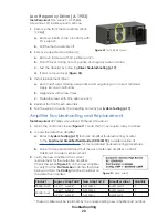
Use the audio system’s Monitor Application to verify all channels of amplifiers and drivers
are functioning correctly. Refer to the
Sportsound Amplifier Field Guide (DD3318172)
,
available online at
, for more information.
1�
With a full-range audio source (music) playing at a moderate level through the
system, click the
Start Monitoring
button.
2�
Click the
Standby Protect
button next to each channel to mute them.
3�
After muting every channel, un-mute one channel at a time and listen for audio.
4�
Un-mute all channels, and stop all source audio from the control rack.
5�
Click the
Test Tone
button for
AMP1
and compare the
Impedance
value (in ohms Ω)
to the reference ranges shown beneath the Channel #.
6�
Repeat Step 5 for all remaining amplifiers. If any impedance values are out of the
reference ranges by half or double, test the individual drivers connected to the
suspect amplifier(s). Refer to
.
Driver Troubleshooting
Tools Required:
flathead screwdriver, Multi-meter,
9V battery
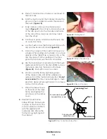
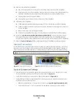
Remove the rear access door on the side of
the cabinet being serviced using the flathead
screwdriver.
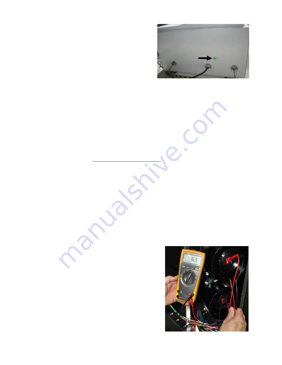
Before removing the driver, verify correct DC
resistance of the driver using a multi-meter
(
). Check the DC resistance of each
driver separately, or check the DC resistance
at the harness. Connect each lead of the multi-
meter to the terminals of the driver (or proper pins
on the harness), and make sure the multi-meter is
set to measure the DC resistance.
Figure 24:
Control Enclosure Power Indicator
Figure 25:
Mid-Frequency Driver & Meter
Содержание SPORTSOUND 500HD
Страница 32: ...This page intentionally left blank ...
Страница 37: ......
Страница 42: ...This page intentionally left blank ...
Страница 50: ...This page intentionally left blank ...
Страница 52: ...This page intentionally left blank ...
Страница 54: ...This page intentionally left blank ...
Страница 58: ...This page intentionally left blank ...


