Operation
www.DaikinApplied.com 39
IOM 1274-3 • CENTRIFUGAL WATER CHILLERS
NOTE:
Timer countdown values will be shown in place of
“xxx”.
For a VFD equipped compressor, “Vanes” or “Speed”
is shown in the RUN state to indicate if the capacity is
controlled by speed from the VFD or by vane control.
The bottom icon bar will be visible on all screens with the
active screen highlighted in white.
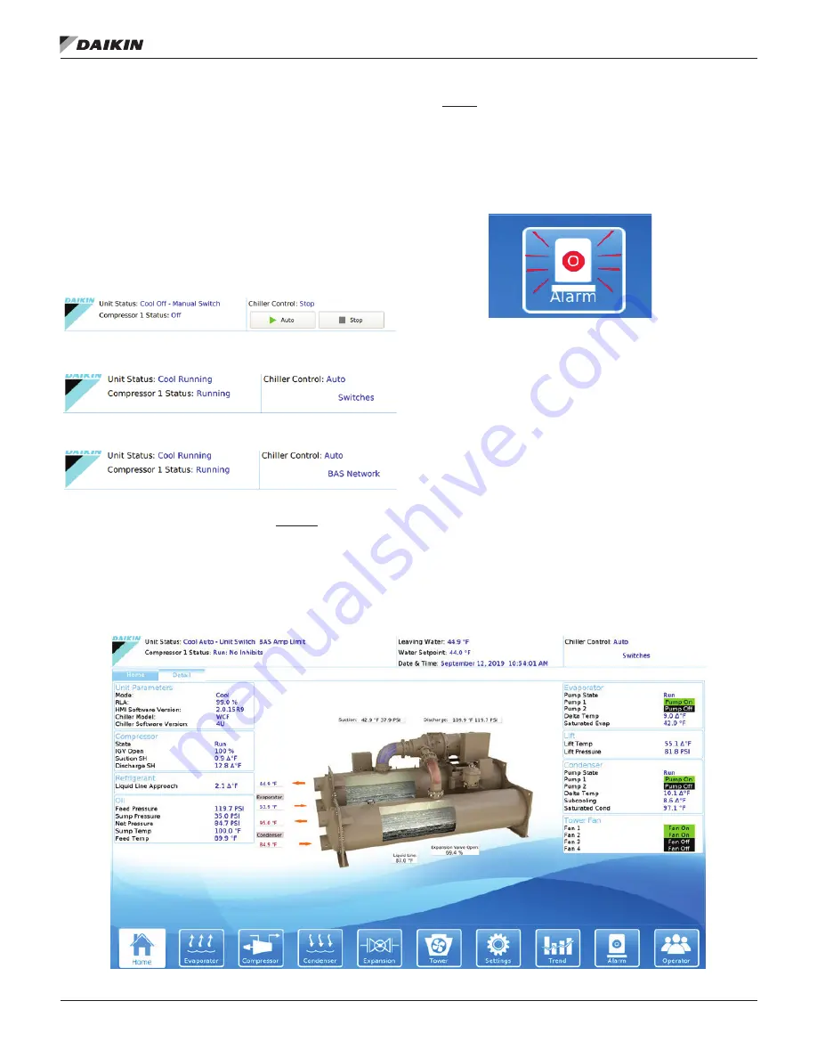
(II) Unit Status Modes
- Defined by Mode followed by State.
If the unit is stopped, the Source would be listed after State.
Various unit states and control sources are shown as examples
in
Figure 38 to Figure 40.
Figure 38: Mechanical Switch Source
Figure 39: Remote Switches Source
Figure 40: BAS Network Source
(III) Additional Home View Trend Data
Graphs
• Entering and leaving evaporator water temperatures
• Entering and leaving condenser water temperatures
• Percent compressor RLA
• Compressor kW (will read 0 without Full Metering Option)
(IV)
Alarm
•
The ALARM icon will turn red and begin flashing should
an alarm occur. This red ALARM button will appear on
all screens in the case of an alarm. See
Figure 41
for an
example of an active alarm alert. For more information on
alarms, see
page 58
.
Figure 41: Active Alarm Icon
Additional HMI View Screens
Pressing the Detail Tab on the top of the Home View Screen
provides specific unit operating parameters shown in
Figure
42
. Chiller Model “WCF” is the general software category for
WSC, WDC, WCC, TSC, TDC, and HSC models (see
“Figure 54: Settings View - Modes” on page 48
).
If a Technician level password is entered, two additional
tabs will follow the Detail Tab. The Tech Data Tab will show
compressor staging and pLAN communication.
On the Tech
I/O Tab, the technician will find all inputs and outputs, both
analog and digital, at both the Unit Controller and Compressor
Controller levels.
To make setpoint adjustments or change operating parameters,
tap on the Settings icon at the bottom of the screen;
Figure 50
on page 46.
Figure 42: Unit Detail View Screen
Содержание WSC
Страница 4: ......
Страница 21: ...Installation www DaikinApplied com 21 IOM 1274 3 CENTRIFUGAL WATER CHILLERS Figure 17 Compressor Control Box ...
Страница 22: ...IOM 1274 3 CENTRIFUGAL WATER CHILLERS 22 www DaikinApplied com Installation Figure 18 Unit Control Box ...
Страница 73: ... www DaikinApplied com 73 IOM 1274 3 CENTRIFUGAL WATER CHILLERS ...
Страница 74: ...IOM 1274 3 CENTRIFUGAL WATER CHILLERS 74 www DaikinApplied com ...


