background image

IOM 1322 • WATER-COOLED SCROLL COMPRESSOR 32 www.DaikinApplied.com


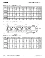
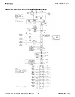
Table 12: Lifting Weights, WGZ030-060D Condenserless

Figure 26: Lifting Locations, WGZ070-130D Condenserless

Table 13: Lifting Weights, WGZ070-130D Condenserless

Lifting and Mounting Weights

Содержание WGZ030DA

Страница 1: ...e Manual Water Cooled Scroll Compressor Chillers WGZ030DW WGZ200DW Packaged Water Cooled Chillers WGZ030DA WGZ200DA Remote Condenser Chillers 30 200 Tons 105 700 kW R 410A 50 60 Hz IOM 1322 Group Chiller Part Number IOM1322 Date June 2021 ...

Страница 2: ...esign and construction at any time without notice Table of Contents Installation and Application Information 5 Water Piping 10 Pressure Drop Data 18 Dimensions and Weights Packaged Units 21 Dimensions and Weights Condenserless Units 25 Lifting and Mounting Weights 30 Unit Controller Operation 44 Startup and Shutdown Procedures 92 Sequence of Operation 97 Unit Maintenance 100 Troubleshooting Chart ...

Страница 3: ...gized at least 12 hours before startup Chiller components EXV Sensors Transducers installed and wired properly Wiring complies with National Electrical Code and local codes See Notes Remote EXV wired with shielded cable Miscellaneous Yes No N A Initials Unit control switches all off Remote Evaporator Condenser Piping factory reviewed All refrigerant components piping leak tested evacuated and char...

Страница 4: ......

Страница 5: ... builds when halo carbon refrigerant travels in a rubber hose A grounding strap must be used between the auxiliary refrigerant tank and the chiller s end sheet earth ground which will safely take the charge to the ground Damage to sensitive electronic components could occur if this procedure is not followed WARNING This equipment generates uses and can radiate radio frequency energy If not install...

Страница 6: ...l contains information on the chiller unit control software operating with various refrigerants as follows 1 R 410A used with the current D vintage of the WGZ chiller 2 R 134a used with only with Model TGZ Templifiers The operating manual devoted exclusively to Templifiers is OMM 1136 Inspection When the equipment is received all items should be carefully checked against the bill of lading to be s...

Страница 7: ...f the unit The clearance for cleaning depends on the type of apparatus used but can be as much as the length of the condenser 10 feet 3050 mm Tube replacement requires the length of the condenser as much as 12 feet plus three feet of workspace This space can be provided via a doorway or other opening Moving the Unit Refer to Lifting Mounting weights beginning on page 30 The packaged unit skid opti...

Страница 8: ...struction should be such that the unit will not affect the building structure or transmit noise and vibration into the structure Isolator pads or spring isolators are available options Mounting All compressor bolts rubber grommets and fasteners should be left in place on the base plate as shown in Figure 2 Compresssor Base Plate Mounting None of these fasteners are considered to be temporary shipp...

Страница 9: ...must be insulated to reduce heat loss and prevent condensation per code requirements Complete unit and system leak tests should be performed prior to insulating the water piping Insulation with a vapor barrier would be the recommended type of insulation The vent and drain connections must extend beyond the proposed insulation thickness for accessibility It is recommended that the field installed w...

Страница 10: ...imes the flow rate GPM is recommended For example if the design chiller flow rate is 120 gpm we recommend a system volume of 240 to 360 gallons For process applications where the cooling load can change rapidly additional system water volume is needed A process example would be the quenching of hot metal objects The load would be very stable until the hot metal is dipped into the water tank Then t...

Страница 11: ...the switch opening in the nozzle 2 Install the grooved to flange adaptor or weld on flange 3 Relocate the flow switch in the water piping outside the flange close enough to it that the wire leads will reach and the switch can still be unscrewed NOTE A water flow switch must be mounted in the evaporator outlet water line to signal that there is water flow before unit will start Glycol Solutions CAU...

Страница 12: ...chemical water treatment on the condenser is recommended immediately upon equipment start up Condensers are drained of water in the factory and are shipped with the condenser drain plugs in the heads removed and stored in a bag in the control panel Be sure to replace plugs prior to filling the vessel with fluid Water cooled condensers can be piped for use with cooling towers well water or heat rec...

Страница 13: ...te Condenser Refrigerant Piping Refrigerant piping to and from the unit and remote components should be sized and installed according to the latest ASHRAE Handbook industry standards and local code requirements It is important that the unit piping be properly supported with sound and vibration isolation between tubing and hanger and that the discharge lines be looped at the condenser and trapped a...

Страница 14: ...er at one time After the equipment is properly installed leak tested and evacuated it can be charged with R 410A and run at design load conditions Total operating charge will depend on the aircooled condenser used and volume of the refrigerant piping NOTE On WGZ DA units units with remote condensers the installer is required to record the refrigerant charge by stamping the total charge and the cha...

Страница 15: ...valve prevents liquid migration to the condenser helps maintain a supply of refrigerant in the liquid line for initial start up and keeps liquid line pressure high enough on off cycle to keep the expansion valve closed If a check valve is necessary there must also be a bypass relief valve to prevent hydrostatic pressure failure Install a relief device in the hot gas piping at the condenser coil as...

Страница 16: ...IOM 1322 WATER COOLED SCROLL COMPRESSOR 16 www DaikinApplied com Table 4 Recommended Liquid Line Size R 410A Table 5 Recommended Horizontal or Downflow Discharge Line Size R 410A Refrigerant Piping ...

Страница 17: ...ipe section should be installed in the line to eliminate any piping stress on the relief valve s Relief valves are located in the following places depending on unit configuration Low side with brazed plate evaporator on the suction line Low side with shell and tube evaporator on the suction line High side on packaged unit on the condenser shell High side on remote condenser if required not factory...

Страница 18: ...following tables Do not include valves or strainers in these readings The evaporator flow rates and pressure drops shown on the following page are for full load design purposes The maximum flow rate and pressure drop are based on a 6 degree temperature drop Avoid higher flow rates with resulting lower temperature drops to prevent potential control problems resulting from very small control bands a...

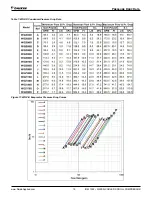
Страница 19: ... www DaikinApplied com 19 IOM 1322 WATER COOLED SCROLL COMPRESSOR Table 7 WGZ D CondenserPressure Drop Data Figure 11 WGZ D Evaporator Pressure Drop Curves Pressure Drop Data ...

Страница 20: ...IOM 1322 WATER COOLED SCROLL COMPRESSOR 20 www DaikinApplied com Table 8 WGZ D Evaporator Pressure Drop Data Components Figure 12 Compressor Locations Pressure Drop Data ...

Страница 21: ... www DaikinApplied com 21 IOM 1322 WATER COOLED SCROLL COMPRESSOR Figure 13 WGZ030DW 060DW Packaged Dimensions and Weights Packaged Units ...

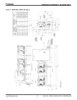
Страница 22: ...IOM 1322 WATER COOLED SCROLL COMPRESSOR 22 www DaikinApplied com Figure 14 WGZ070DW Packaged Dimensions and Weights Packaged Units ...

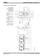
Страница 23: ... www DaikinApplied com 23 IOM 1322 WATER COOLED SCROLL COMPRESSOR Figure 15 WGZ080DW 130DW Packaged Dimensions and Weights Packaged Units ...

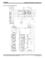
Страница 24: ...IOM 1322 WATER COOLED SCROLL COMPRESSOR 24 www DaikinApplied com Figure 16 WGZ150DW 200DW Packaged Dimensions and Weights Packaged Units ...

Страница 25: ... www DaikinApplied com 25 IOM 1322 WATER COOLED SCROLL COMPRESSOR Figure 17 WGZ030DA 060DA Condenserless Dimensions and Weights Condenserless Units ...

Страница 26: ...IOM 1322 WATER COOLED SCROLL COMPRESSOR 26 www DaikinApplied com Figure 18 WGZ070DA Condenserless Dimensions and Weights Condenserless Units ...

Страница 27: ... www DaikinApplied com 27 IOM 1322 WATER COOLED SCROLL COMPRESSOR Figure 19 WGZ080DA 130DA Condenserless Dimensions and Weights Condenserless Units ...

Страница 28: ...IOM 1322 WATER COOLED SCROLL COMPRESSOR 28 www DaikinApplied com Figure 20 WGZ150DA 200DA Condenserless see next page for more dimensions Dimensions and Weights Condenserless Units ...

Страница 29: ... www DaikinApplied com 29 IOM 1322 WATER COOLED SCROLL COMPRESSOR Figure 21 WGZ150DA 200DA Condenserless continued Dimensions and Weights Condenserless Units ...

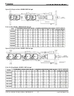
Страница 30: ...30 www DaikinApplied com Figure 22 Lifting Locations WGZ030 060D Packaged Table 9 Lifting Weights WGZ030 060D Packaged Figure 23 Lifting Locations WGZ070 130D Packaged Table 10 Lifting Weights WGZ070 130D Packaged Lifting and Mounting Weights ...

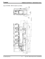
Страница 31: ...g the Unit on page 7 for details on transferring lifting the unit Do not lift unit by mounting holes in feet Figure 24 Lifting Locations WGZ150 200D Packaged Table 11 Lifting Weights WGZ150 200D Packaged Figure 25 Lifting Locations WGZ030 060D Condenserless Lifting and Mounting Weights ...

Страница 32: ...ROLL COMPRESSOR 32 www DaikinApplied com Table 12 Lifting Weights WGZ030 060D Condenserless Figure 26 Lifting Locations WGZ070 130D Condenserless Table 13 Lifting Weights WGZ070 130D Condenserless Lifting and Mounting Weights ...

Страница 33: ... www DaikinApplied com 33 IOM 1322 WATER COOLED SCROLL COMPRESSOR Figure 27 Lifting Locations WGZ150 200D Condenserless Table 14 Lifting Weights WGZ150 200D Condenserless Lifting and Mounting Weights ...

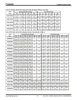
Страница 34: ...501 332325501 332325501 332325505 Table 16 Vibration Isolator Mounting Locations Packaged Chillers Transfer the unit as indicated under Moving the Unit In all cases set the unit in place and level When spring type isolators are required install springs running under the main unit supports The unit should be set initially on shims or blocks at the listed spring free height When all piping wiring fl...

Страница 35: ...lied com 35 IOM 1322 WATER COOLED SCROLL COMPRESSOR Table 17 Vibration Isolator Mounting Locations Packaged Chillers continued Table 18 Vibration Isolator Mounting Locations Condenserless Chillers Vibration Isolators ...

Страница 36: ...IOM 1322 WATER COOLED SCROLL COMPRESSOR 36 www DaikinApplied com Table 19 Physical Data WGZ030D WGZ040D Table 20 Physical Data WGZ045D WGZ055D Physical Data Packaged Units ...

Страница 37: ... www DaikinApplied com 37 IOM 1322 WATER COOLED SCROLL COMPRESSOR Table 21 Physical Data WGZ060D WGZ070D Table 22 Physical Data WGZ080D WGZ090D Physical Data Packaged Units ...

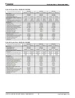
Страница 38: ...IOM 1322 WATER COOLED SCROLL COMPRESSOR 38 www DaikinApplied com Table 23 Physical Data WGZ100D WGZ130D Table 24 Physical Data WGZ150D WGZ200D Physical Data Packaged Units ...

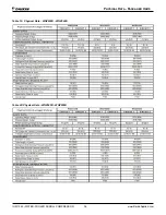
Страница 39: ...Physical Data WGZ030D WGZ040D NOTE Condenser and field piping not included Table 26 Physical Data WGZ045D WGZ055D NOTE Condenser and field piping not included Table 27 Physical Data WGZ060D WGZ070D NOTE Condenser and field piping not included Physical Data Units Less Condenser ...

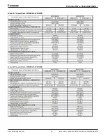
Страница 40: ...hysical Data WGZ080D WGZ090D NOTE Condenser and field piping not included Table 29 Physical Data WGZ100D WGZ130D NOTE Condenser and field piping not included Table 30 Physical Data WGZ150D WGZ200D NOTE Condenser and field piping not included Physical Data Units Less Condenser ...

Страница 41: ... values given in table apply to 75 C rated wire per NEC Supplemental Overloads Option The supplemental overloads option is used to reduce the required electrical service size and wire sizing cost to the water cooled version of WGZ chillers The overloads reduce the electrical requirements for the chiller because water cooled duty requires less power than air cooled duty The overload option is only ...

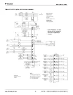
Страница 42: ...IOM 1322 WATER COOLED SCROLL COMPRESSOR 42 www DaikinApplied com Figure 29 Field Wiring Diagram Packaged Units Electrical Data ...

Страница 43: ... www DaikinApplied com 43 IOM 1322 WATER COOLED SCROLL COMPRESSOR Figure 30 Field Wiring Diagram Units less condenser Electrical Data ...

Страница 44: ...rol panel with associated sensors and transducers Models WGZ 150 to WGZ 200 have two refrigerant circuits two trio scroll compressors total of six a single two circuited shell and tube evaporator a single two circuited water cooled condenser interconnecting refrigerant piping and a control panel with associated sensors and transducers Figure 31 Schematic Piping Diagram One of Two Circuits for WGZ0...

Страница 45: ... www DaikinApplied com 45 IOM 1322 WATER COOLED SCROLL COMPRESSOR Field Wiring Diagrams Figure 32 WGZ030DW WGZ200DW Field Wiring Diagram Packaged Unit Unit Configuration ...

Страница 46: ...IOM 1322 WATER COOLED SCROLL COMPRESSOR 46 www DaikinApplied com Figure 33 WGZ030DA WGZ200DA Field Wiring Diagram Remote Condenser Unit Configuration ...

Страница 47: ...l door Motor Protection Module The motor protection system consists of an external control module located on each compressor motor terminal box connected to a series of thermistors located in the motor windings and the compressor discharge port If the windings experience an over temperature condition or the discharge temperature is excessive the module will trip and shut off the compressor WARNING...

Страница 48: ...stamp are retained in memory and can be easily displayed in plain English for operator review which is an extremely useful feature for troubleshooting In addition to displaying alarm diagnostics the MicroTech II chiller controller also provides the operator with a warning of pre alarm conditions Staging The four scroll or six compressors are staged on and off as a function of leaving chilled water...

Страница 49: ...TE 2 Selection of R134a in unit setpoint screen will modify unit operation for Templifier application Table 42 Analog Outputs Description Output Signal Range 1 Cooling Tower Bypass Valve Position 0 to 10 VDC 0 to 100 Open 2 Cooling Tower VFD Speed 0 to 10 VDC 0 to 100 3 Circuit 1 Electronic Expansion Valve 0 to 10 VDC 0 to 100 4 Circuit 2 Electronic Expansion Valve 0 to 10 VDC 0 to 100 NOTE Analog...

Страница 50: ...C Fault 24 VAC No Fault 16 Open 16 Motor Protection 2 R134a R410A C2 0 VAC Fault 24 VAC No Fault 17 Ice Mode Switch UT 0 VAC Normal 24 VAC Ice 18 Heat Mode Switch UT 0 VAC Normal 24 VAC Heat NOTE 1 See Safety Alarms Table for Phase Voltage Protection Units with single point electrical connection will have one PVM with Inputs 9 and 10 wired together Units with multiple point connection will have tw...

Страница 51: ...nser Fan 6 C2 Fan Contactor Fan OFF Fan ON 16 Condenser Fan 4 C2 Fan Contactor Fan OFF Fan ON 17 Condenser Fan 7 C1 Fan Contactor Fan OFF Fan ON 17 Condenser Fan 5 7 R134a R410A C1 Fan Contactor Fan OFF Fan ON 18 Condenser Fan 8 C2 Fan Contactor Fan OFF Fan ON 19 Condenser Fan 6 8 C2 Fan Contactor Fan OFF Fan ON Expansion I O Controller Digital Outputs The following parameters are digital outputs ...

Страница 52: ...actory set to the Default value and can be adjusted to any value in the Range column The PW password column indicates the password level that must be active in order to change the setpoint Passwords are as follows O Operator 0100 M Manager 2001 Table 45 Setpoints setpoints with are set at Daikin Applied factory Unit Controller Operation ...

Страница 53: ...nApplied com 53 IOM 1322 WATER COOLED SCROLL COMPRESSOR NOTE Temperature sensor SO 5 is Condenser Entering water sensor when Water Cooled ON and Outdoor Air sensor when Water Cooled OFF Unit Controller Operation ...

Страница 54: ...cooled applications Dynamic Defaults Some set points will have a particular default value loaded when another setting is changed Refrigerant Dependent Defaults AC Air Cooled WC Water Cooled R134a is water cooled ONLY Number of Fans Dependent Defaults When the number of fans setting is changed the forced fan set points will default to values as shown in the following table Events Alarms Situations ...

Страница 55: ...Run state which will clear the alarm After three occurrences the count of occurrences is reset and the cycle starts over if the manual reset flow loss alarm is cleared If active via trigger condition 2 If the flow loss alarm has occurred due to this trigger it is always a manual reset alarm Low Evaporator Pressure Alarm description as shown on screen Evap Press Low Cir N Trigger Circuit State Run ...

Страница 56: ...operating in heat mode Action Taken Normal stop all circuits Reset This alarm can be cleared manually via the keypad but only if the sensor is back in range Suction Temperature Sensor Fault Alarm description as shown on screen SuctT Sensor Fail N Trigger Sensor shorted or open AND Expansion Valve Type Electronic Action Taken Rapid stop circuit Reset This alarm can be cleared manually via the keypa...

Страница 57: ...ust be cleared at the unit controller To clear active alarms scroll down to the end of the Active Alarm list press Enter to clear all active alarms If the user attempts to clear an alarm while the alarm condition still exists a new alarm will be generated immediately Limit Events The following events do not cause a rapid stop but limit operation of the chiller in some way as described in the Actio...

Страница 58: ... Reset Cond Sat Refr Temp Condenser Freeze Set Point plus 2 F Suction Temperature Sensor Fail Event description as shown on screen SuctT Sensor Fail N Trigger Sensor shorted or open Action Taken None Reset N A Entering Evaporator Water Temperature Sensor Fail TGZ unit only Event description as shown on screen Evap EWT Sensor Fail Trigger Sensor shorted or open Action Taken None Reset N A Liquid Li...

Страница 59: ...t modes the compressor staging temperatures are calculated as shown below Stage Up Temperature Cool LWT Control Band 2 Stage Down Temperature Cool LWT Control Band 2 The Cool Start up and Shutdown temperatures are calculated from the Control Band The Start Up temperature determines when the first compressor on the unit will start The Start Up temperature calculation is shown below Start Up Tempera...

Страница 60: ...ax Reset set points if the reset signal equals or exceeds 20 mA The amount of reset will vary linearly between these extremes if the reset signal is between 4 mA and 20 mA An example of the operation of 4 20 mA reset in Heat mode is shown below Reset Type Return only for TGZ unit Refrig R134a Cooling Mode The Active Cooling Leaving Water set point is adjusted based upon the difference between the ...

Страница 61: ... Evaporator Saturated Temperatures Templifiers only When R134a refrigerant is selected the refrigerant pressure will be fitted to a curve made up of 12 straight line segments The accuracy of calculated saturated temperatures is 0 5º F when compared to standard look up tables for R134a refrigerant Condenser Saturated Temperature Condenser saturated temperature shall be calculated from the condenser...

Страница 62: ...lycol SWITCHES ON X X COOL ICE w Glycol ICE w Glyco KEYPAD X COOL w Glycol X COOL ICE w Glycol COOL w Glycol KEYPAD X CE w Glyco X COOL ICE w Glycol ICE w Glyco NETWORK X X COOL COOL ICE w Glycol COOL w Glycol NETWORK X X ICE COOL ICE w Glycol ICE w Glycol X X X X ICE w Glyco ICE w Glycol X X X X TEST TEST Unit Test Mode The unit test mode allows manual testing of controller outputs Entering this ...

Страница 63: ...ble Off OR Remote Switch Off OR T3 Pumpdown to Off Unit Alarm OR Unit Switch Off OR No Compressors Running T4 Auto to Off Unit Alarm OR Unit Switch Off OR No Compressors Running AND Unit Mode Ice AND Ice Delay Active OR No Compressors Running AND No Circuit Available Figure 36 Unit State Diagram Evaporator Water Pump State Control Evap State The state transition diagram shown below controls operat...

Страница 64: ... Alarm indicator is turned off and the unit resumes normal startup procedures based on water temperature and cycle timers If second Evaporator Water Flow Loss occurs within twenty four hours the process described above is repeated If a third loss of flow is indicated in a twenty four hour time frame the unit will shut down on an Evaporator Water Flow Loss alarm and it will be locked out until this...

Страница 65: ... rises back within the Stage Down dead band the Stage Down Error Accumulator is reset to zero Forced Fan Stage at Start Fans may be started simultaneously with the compressor based on outdoor ambient temperature When the compressor starts and after compressor operation is verified by either a 1 psi drop in evaporator or 1 psi rise in condenser pressures a Fantrol stage is forced based on the follo...

Страница 66: ...second Condenser Water Flow Loss occurs within twenty four hours the process described above is repeated If a third loss of flow is indicated in twenty four hour time frame the Unit will shut down on an Condenser Water Flow Loss alarm and it will be locked out until this alarm is manually cleared The twenty four hour timer that limits the auto restart is reset when the control clock rolls over 00 ...

Страница 67: ... Control set point is set to Valve Stage In this mode the valve output is controlled as for Valve Set Point mode above except that the active set point for the controlled parameter is selected according to the following table Number Of Fans ON Active Set Point 0 Valve Set Point 1 Stage 1 ON 2 Stage 2 ON Cooling Tower Fan VFD When the Valve VFD Control set point is set to None Valve Setpoint OR Val...

Страница 68: ...ator pressure is 20 0 psi When the Low OAT Start Timer has expired if the evaporator pressure is greater than or equal to the Low Evaporator Pressure Unload set point the start is considered successful and normal alarm and event logic is reinstated If the evaporator pressure is less than the Low Evaporator Pressure Unload set point when the Low OAT Start Timer expires the start is unsuccessful and...

Страница 69: ... fully loaded both compressors running when that circuit s condenser pressure exceeds the High Condenser Pressure Unload set point Circuit number one will unload by turning one of the two compressors off immediately This circuit will not be allowed to load back up until its condenser pressure decreases below the Hold Clear value which is displayed on the VIEW CIRCUIT 1 1 screen Since this is the f...

Страница 70: ...ed compressor offline while the remaining compressors on the circuit can still provide some cooling A running compressor cannot be disabled until it has been shutdown If both of the compressors on a circuit have been disabled then the circuit is disabled If both circuits have all of their compressors disabled the Unit state will remain Off Normal Circuit Shutdown If a condition arises that require...

Страница 71: ...edures to learn in order to utilize the MicroTech II controller Navigating through the menu matrix to reach a desired menu screen and knowing where a particular screen is located Knowing what is contained in a menu screen and how to read that information or how to change a setpoint contained in the menu screen Navigating Through the Menus The menus are arranged in a matrix of screens across a top ...

Страница 72: ...ER key to enter it Nothing is changed until the ENTER key is pressed For example to change the chilled water setpoint 1 Press MENU key to go to the MENU mode 2 Press SET the UP Key to go to the setpoint menus 3 Press UNIT SPs the Right key to go to setpoints associated with unit operation 4 Press the DOWN key to scroll down through the setpoint menus to the third menu which contains Evap LWT XX X ...

Страница 73: ...d N No This selection will alter some menus as appropriate to the type of condenser Screen Definitions MENU Unit states can be OFF COOL GYLCOL ICE or ALARM as determined from the Unit Mode setpoint the Unit Enable and the presence of an alarm Circuit states can be OFF OFF ON OFF OFF ON and ON ON Evaporator Pump States can be OFF STRT or RUN When more than one screen are stacked i e relate to each ...

Страница 74: ...cooled units and the TGZ units will give the entering condenser water temperature and air cooled units will give the outside air temperature OAT The outside air temperature sensor is furnished with the unit inside the control panel wired to the correct terminals It must be installed outdoors in a location that will give the true outdoor temperature that the condenser coils will see Splicing of the...

Страница 75: ...Unit Controller Operation www DaikinApplied com 75 IOM 1322 WATER COOLED SCROLL COMPRESSOR ...

Страница 76: ...IOM 1322 WATER COOLED SCROLL COMPRESSOR 76 www DaikinApplied com Unit Controller Operation ...

Страница 77: ...ages ON value is the number of fan stages ON The second number is the Tower Stages setpoint 0 if Tower Control None This screen shows the number of tower fans on for each circuit This screen will show the fans on whether they are actually connected to and controlled by the MicroTech II controller or not ...

Страница 78: ...n and press ENTER If other faults have appeared they will all be cleared at the same time It is not necessary to have a password open to clear alarms ALARM LOG X Alarm Description Time Date Data Edit and scroll The last 25 alarms either shutdown or limit are shown in this menu and subsequent menus located under it ARROW DOWN from this menu will go to the next to last alarm ARROW DOWN again will go...

Страница 79: ...p Recirc XXX sec Evap Pump 1 Only TGZ Units Only R134a SET UNIT SPs 5 Max Pulldn X X F min Evap Recirc XXX sec Evap Pump 1 Only Evap Pump choices are 1 Only 2 Only Auto 1 Primary 2 Primary Water Cooled ON SET UNIT SPs 6 Water Cooled ON Cond Recirc XXX sec Cond Pump 1 Only Water Cooled OFF SET UNIT SPs 6 Water Cooled Off LowAmbLock XXX X F TGZ Units R134a SET UNIT SPs 6 Water Cooled Off LowAmbLock ...

Страница 80: ...or Offset 00 0 F TGZ Units Refrig R134a SET UNIT SPs 14 LWT Sensors Evap Offset 00 0 F Cond Offset 00 0 F SET UNIT SPs 15 Suction Temp Sensor Cir1 Offset 00 0 F Cir2 Offset 00 0 F WGZ Unit R410A SET UNIT SPs 16 Clg ResType X Clg MaxRes XX X ºF TGZ Unit Refrig 134a SET UNIT SPs 16 Liq Line Temp Sensors Circ1 Offset 00 0 ºF Circ2 Offset 00 0 ºF WGZ Unit R410A SET UNIT SPs 17 ENTER PASSWORD XXXX Acti...

Страница 81: ...geDn is the time delay since the last stage change before a compressor can stage off normally not by an alarm Default is 30 sec It is recommended that these settings not be changed of Compressors 4 SET COMP SPs 3 Comp 1 Enable Comp 3 Enable of Compressors 6 SET COMP SPs 3 Comp 1 Enable Comp 3 Enable Comp 5 Enable of Compressors 4 SET COMP SPs 4 Comp 2 Enable Comp 4 Enable of Compressors 6 SET COMP...

Страница 82: ...with air cooled condensers and prevents unit operation below the setting The available range is 2 F to 60 F with a default of 35 F WaterCooled ON SET ALARM LIMITS 5 Cond Freeze XX X F CondFlowProof XX sec TGZ in Heat Mode SET ALARM LIMITS 6 LowSourceTmp XX X F LowSourceDif XX X F Set Air Cooled Condenser Fans Water cooled Off SET FANS SPs 1 Fan Stages X Speedtrol Yes No Water cooled Off SET FANS S...

Страница 83: ... DN imposes a time delay between fan stages when turning on or turning off Water cooled On SET TOWER SPs 2 Stage ON Temp F 1 2 XXX XXX Stage ON Temp is the entering condenser water temperature ECWT that will turn on tower fan 1 and 2 Default settings are 70 F and 75 F Cold condenser water will improve unit efficiency but too cold can cause erratic operation Settings below 60 F are not recommended ...

Страница 84: ...tings establish the operation of a tower bypass valve must be a 3 way valve Initial Valve Position When the condenser pump is not in the RUN state the valve output shall be set as a function of entering condenser water temperature ECWT per the following graph Figure 41 Initial Valve Position Operation After Start When the condenser pump is in the RUN state the valve output shall be controlled in o...

Страница 85: ...NCEL Right Reset the current field to the value it had when editing began DEFAULT Left Set value to original factory setting INCREMENT Up Increase the value or select the next item in a list DECREMENT Down Decrease the value or select the previous item in a list During edit mode the display shall show a two character wide menu pane on the right as shown below SET UNIT SPs X D data C data data Addi...

Страница 86: ...ain valid for 15 minutes after the last key press BAS Interface The BAS interface will use the supervisor port on the controller as a connection point Protocols Supported The following building automation system BAS protocols are supported It is possible to change the building automation interface without loading different software BACnet When protocol is set to BACnet the baud rate and ident set ...

Страница 87: ...COMPRESSOR Parameter Details Units of Measure Parameters will be expressed in different units dependant on the protocol selected Parameter Type Modbus Units BACnet Units LONworks Units Temperature F X 10 F X 10 C X 100 Pressure PSI X 10 PSI X 10 KPa X 10 Percentage X 10 X 10 X 200 ...

Страница 88: ...he version and the remaining part represents the revision letter Compressor Select Compressor Select is used to select the compressor for which the associated parameters will be sent to the BAS interface The input should equal the number of the compressors for which data is desired If a 0 is sent from the BAS this will also select compressor 1 Timeclock Setting The chiller time and date may be cha...

Страница 89: ... and switches D 3 O Active alarm indicator Set when any alarm is active Active events do not set this output D 4 O Chiller run enabled Set when the unit state is auto D 5 O Chiller local control Set when the unit control source is set to keypad or switches D 6 O Chiller capacity limited Set when a unit capacity limit is active any circuit is disabled or any circuit is limited in capacity D 7 O Eva...

Страница 90: ...s are accumulated in 24 hours the Warning code will be cleared Code 4 Open Shorted Scroll Thermistor The module will flash the green Warning LED four times indicating the scroll NTC thermistor has a resistance value that indicates an open shorted thermistor see Table 2 The Warning will be cleared when the resistance value is in the normal range Alert Lockout Codes Red LED Flash Code Code 1 Motor H...

Страница 91: ...e phase electrical motor loss due to power failure conditions phase loss and phase reversal Whenever any of these conditions occur an input relay is deactivated disconnecting power to the thermostatic control circuit The compressor does a rapid shutdown including a pump down cycle The input relay remains deactivated until power line conditions return to an acceptable level Trip and reset delays ha...

Страница 92: ...glass located in the equalizing line between the compressors or on the compressor 9 Check water pressure drop across evaporator and condenser and see that water flow is correct beginning on page 18 per the design flow rates 10 Check the actual line voltage to the unit to make sure it is the same as called for on the compressor nameplate within 10 and that phase voltage unbalance does not exceed 2 ...

Страница 93: ...xtended Shutdown 1 Inspect all equipment to see that it is in satisfactory operating condition 2 Remove all debris that has collected on the surface of the condenser coils remote condenser models or check the cooling tower if present 3 Open the compressor discharge valves until backseated Always replace valve seal caps 4 Open the manual liquid line shutoff valves 5 5 Check circuit breakers They mu...

Страница 94: ...pipe is necessary contact Chiller Technical Response at TechResponse DaikinApplied com to review the jobsite details NOTE DO NOT alter or relocate factory installed flow switches If issues exist contact Chiller Technical Response at TechResponse DaikinApplied com Figure 45 Remote Mounting Guidelines for Flow Switch If needed the adapter is threaded into the pipe using pipe sealant appropriate for ...

Страница 95: ... 46 Flow Volume Calculation Step 3 After the Teach function is completed and the outer LEDs flashed the flow switch will indicate a new set point based upon the current flow which should still be at the steady state minimum desired operating flow Figure 47 shows a typical display for this condition All LEDs to the left of the SP LED are lit green The SP LED is lit RED or may toggle amber which ind...

Страница 96: ...e same procedure is performed to toggle to unlocked NOTE 1 The LED window display on flow switch represents a velocity range of 50 cm s The window centers on the set point SP For example if the SP was set to 200 cm s then the LED labeled 0 would represent a velocity of 180 cm s when lit and the LED labeled 9 would represent a velocity of 230 cm s when lit 2 Each LED represents 5 cm s or two presse...

Страница 97: ... out additional compressors will stage off The last compressor will stage off when the LWT falls below the LWT Setpoint minus the Dead Band minus the Stop Delta T The stop Delta T is in effect for only the last compressor running If the temperature climbs above 38 5 F all running compressors will remain on No compressor staging occurs within the Dead Band The next on compressor will start when the...

Страница 98: ... cooling The Compressor Disable set points are found on Compressor Set Points screens three and four A running compressor cannot be disabled until it has been shutdown If all of the compressors on a circuit are disabled then the circuit will be disabled If both circuits have all of their compressors disabled then the Unit State will remain Off Automatic Pump Down WGZ units are equipped with single...

Страница 99: ...ections on the pressure settings can be found on page 65 The following charts illustrate how four controller outputs can control six fan steps ICE In ICE mode the compressors stage to 100 load until the LWT is less than the ICE LWT SP Then Compressors 3 and 4 shut down Following that Compressors 1 and 2 shut down after going through normal pumpdown on both circuits There is a programmable start to...

Страница 100: ...ld also provide an indication of excessive pressure drop through the filter drier and solenoid valve due to a clogging filter drier Note A normal pressure drop through the solenoid valve is approximately 3 psig 20 7 kPa at full load condition DANGER LOCKOUT TAGOUT all power sources prior to servicing the unit Disconnect all power before doing any service inside the unit or serious personal injury ...

Страница 101: ... compressor If the crankcase is cool below 80 F 26 7 C and the oil level in the sight glass is full to top allow more time for oil to warm before starting the compressor The crankcase heaters are on whenever power is supplied to the unit and the compressor is not running Phase Voltage Monitor Optional The phase voltage monitor is a device that provides protection against three phase electrical mot...

Страница 102: ...f its mounting stud for replacement Be sure to replace the coil on its mounting stud before returning the pumpdown switch to the auto pumpdown position To replace the entire solenoid valve follow the steps for changing a filter drier Thermostatic Expansion Valve The expansion valve is responsible for allowing the proper amount of refrigerant to enter the evaporator regardless of cooling load It do...

Страница 103: ... www DaikinApplied com 103 IOM 1322 WATER COOLED SCROLL COMPRESSOR Maintenance Schedule ...

Страница 104: ...IOM 1322 WATER COOLED SCROLL COMPRESSOR 104 www DaikinApplied com Troubleshooting Chart ...

Страница 105: ... www DaikinApplied com 105 IOM 1322 WATER COOLED SCROLL COMPRESSOR Warranty Registration Form Scroll ...

Страница 106: ...IOM 1322 WATER COOLED SCROLL COMPRESSOR 106 www DaikinApplied com Warranty Registration Form Scroll ...

Страница 107: ... www DaikinApplied com 107 IOM 1322 WATER COOLED SCROLL COMPRESSOR Warranty Registration Form Scroll ...

Страница 108: ...IOM 1322 WATER COOLED SCROLL COMPRESSOR 108 www DaikinApplied com Warranty Registration Form Scroll ...

Страница 109: ... www DaikinApplied com 109 IOM 1322 WATER COOLED SCROLL COMPRESSOR Warranty Registration Form Scroll ...

Страница 110: ...IOM 1322 WATER COOLED SCROLL COMPRESSOR 110 www DaikinApplied com Warranty Registration Form Scroll ...

Страница 111: ... www DaikinApplied com 111 IOM 1322 WATER COOLED SCROLL COMPRESSOR Limited Product Warranty ...

Страница 112: ...uant to its standard terms and conditions of sale including Limited Product Warranty Consult your local Daikin Applied Representative for warranty details To find your local Daikin Applied Representative go to www DaikinApplied com Aftermarket Services To find your local parts office visit www DaikinApplied com or call 800 37PARTS 800 377 2787 To find your local service office visit www DaikinAppl...

Отзывы: