


9 Maintenance and service
Installer and user reference guide
43
SERHQ020~0 SEHVX20~64BAW
Split packaged air-cooled water chiller
4P508020-1B – 2018.04
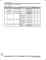
Main code
Cause
Solution
The stop valve of the outdoor unit is left closed.
Open the stop valve on both the gas and liquid side.
Refrigerant overcharge.
Recalculate the required amount of refrigerant from the
piping length and correct the refrigerant charge level by
recovering any excessive refrigerant with a refrigerant
recovery machine.
Insufficient refrigerant.
Check if the additional refrigerant charge has been finished
correctly. Recalculate the required amount of refrigerant
from the piping length and add an adequate amount of
refrigerant.
Reversed power supply phase malfunction.
Correct phase order.
No power is supplied to the outdoor unit.
Check if the power wiring for the outdoor unit is connected
correctly.
The piping and wiring of the specified indoor unit are not
connected correctly to the outdoor unit.
Confirm that the piping and wiring of the specified indoor unit
are connected correctly to the outdoor unit.
After correcting the abnormality, press BS3 and reset the error code.
Carry out the test operation again and confirm that the abnormality is
properly corrected.
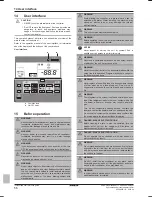
8.8
Checklist handover to the user
Mark the following actions when the installation is finished and the
test run is complete.
Complete the model fill-in for each unit
Ensure the user has a printed version of the installation
and operation manual.
Explain to the user what system is installed on site.
Explain to the user how to properly operate the system
and what to do in case of problems.
Show the user what has to be done in relation to
maintenance of the unit.
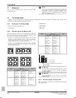
8.9
To complete the model fill-in
Complete the following fill-in for each unit:
Place of
Installation:
Model name (see
nameplate of unit):
Optional
equipment:
Date:
Signature:
Your product was
installed by:
9
Maintenance and service
NOTICE
Maintenance MUST be done by an authorized installer or
service agent.
We recommend performing maintenance at least once a
year. However, applicable legislation might require shorter
maintenance intervals.
NOTICE
In Europe, the
greenhouse gas emissions
of the total
refrigerant charge in the system (expressed as tonnes CO
2
equivalent) is used to determine the maintenance intervals.
Follow the applicable legislation.
Formula to calculate the greenhouse gas emissions:
GWP value of the refrigerant × Total refrigerant charge [in
kg] / 1000
9.1
Overview: Maintenance and
service
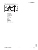
This chapter contains information about:
▪ Preventing electrical hazards when maintaining and servicing the
system
▪ Vacuuming the system
▪ The refrigerant recovery operation
▪ The yearly maintenance of the indoor unit
9.2
Maintenance safety precautions
DANGER: RISK OF ELECTROCUTION
DANGER: RISK OF BURNING
NOTICE: Risk of electrostatic discharge
Before performing any maintenance or service work, touch
a metal part of the unit in order to eliminate static electricity
and to protect the PCB.
Содержание SERHQ020BAW1
Страница 68: ......
Страница 69: ......
Страница 70: ......
Страница 71: ......
Страница 72: ...4P508020 1B 2018 04 Copyright 2018 Daikin...


