background image

5 Preparation

Installer and user reference guide

14

SERHQ020~0 SEHVX20~64BAW

Split packaged air-cooled water chiller

4P508020-1B – 2018.04

▪ The  maximum  water  piping  temperature  is  50°C  according  to

safety device setting.

▪ Always use materials which are compatible with the water used in

the system and with the materials used in the unit. (The unit piping
fittings are made of brass, the plate heat exchangers are made of
stainless  steel  316  plates  brazed  together  with  copper  and  the
optional pump housing is made of cast iron.)

▪ Select  the  piping  diameter  in  relation  to  the  required  water  flow

and available external static pressure (ESP) of the pump. See the
following table for the recommended water piping diameter.

Capacity class

Water piping diameter

20+32

1-1/4"

40+64

2"

NOTICE

It is strongly recommended to install an additional filter on
the  water  circuit.  Especially  to  remove  metallic  particles
from the field water piping, it is advised to use a magnetic
or  cyclone  filter  which  can  remove  small  particles.  Small
particles  can  damage  the  unit  and  will  not  be  removed  by
the standard filter of the unit.

5.4.2

Formula to calculate the expansion vessel
pre-pressure

The  pre-pressure  (Pg)  of  the  vessel  depends  on  the  installation
height difference (H):

Pg=0.3+(H/10) (bar)

5.4.3

To check the water volume and expansion
vessel pre-pressure

The  unit  has  an  expansion  vessel  of  12  litre  with  a  default  pre-
pressure of 1 bar.

To make sure that the unit operates properly:

▪ You must check the minimum and maximum water volume.

▪ You  might  need  to  adjust  the  pre-pressure  of  the  expansion

vessel.

Minimum water volume

Model

Minimum total water volume (l)

20

76

32

110

40

152

64

220

INFORMATION

In  critical  processes,  or  in  rooms  with  a  high  heat  load,
extra water might be required.

INFORMATION

The  temperature  step  difference  can  be  modified  using
settings  [A‑02]  and  [F‑00].  This  has  an  impact  on  the
minimum water volume required when the unit operates in
cooling.

By  default,  the  unit  is  set  to  have  a  water  temperature
difference  of  3.5  K  which  allows  it  to  operate  with  the
minimum  volume  mentioned  in  the  previous  table.
However,  if  a  smaller  temperature  differential  is  set,  as  in
the  case  of  process  cooling  applications  where
temperature  fluctuations  must  be  avoided,  a  larger
minimum water volume will be required.

To ensure proper operation of the unit when changing the
values  of  setting  [F‑00]  (for  cooling  mode),  the  minimum
water  volume  has  to  be  corrected.  If  this  volume  exceeds
the  range  allowed  in  the  unit,  an  additional  expansion
vessel or a buffer tank must be installed in the field piping.

Example: 

To  illustrate  the  impact  on  the  system  when  modifying  the  setting
[F‑00],  we  will  consider  a  unit  with  a  minimum  allowable  water
volume  of  66  l.  The  unit  is  installed  5  m  below  the  highest  point  in
the water circuit.

Assuming that the setting [F‑00] is changed from 5°C (default value)
to  0°C.  From  the  below  table  we  see  that  5°C  corresponds  to  a
temperature differential of 3.5 K and 0°C to 1 K, which is actually the
lowest value we can set.

[F‑00] value (°C)

Temperature differential (K)

0

1

1

1.5

2

2

3

2.5

4

3

5

3.5

6

4

7

4.5

8

5

9

5.5

10

6

11

6.5

12

7

13

7.5

14

8

15

8.5

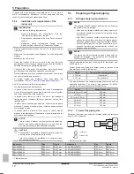
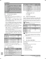
The water volume correction factor according to the curve shown in
the below graph is 3.5; this means that the minimum volume will be
3.5 times larger.

Correction factor curve for minimum water volume

0.0

0.5 

1.0

1.5

2.0

2.5

3.0

3.5

4.0

0

0.5 1

1.5 2

2.5 3 3.5 4 4.5  5

5.5 6

6.5 7 7.5 8 8.5 9

a

b

a

Water volume correction factor

b

Temperature differential (K)

Содержание SERHQ020BAW1

Страница 1: ...user reference guide Split packaged air cooled water chiller English Installer and user reference guide Split packaged air cooled water chiller SERHQ020BAW1 SERHQ032BAW1 SEHVX20BAW SEHVX32BAW SEHVX40B...

Страница 2: ...component box of the outdoor unit 17 6 2 5 To open the electrical component box of the indoor unit 18 6 3 Mounting the outdoor unit 18 6 3 1 About mounting the outdoor unit 18 6 3 2 Precautions when m...

Страница 3: ...m 59 16 3 3 Space cooling operation 59 16 3 4 Space heating operation 59 16 3 5 Other operation modes 60 16 3 6 Schedule timer 60 16 3 7 Operating the optional demand PCB 64 16 3 8 Operating the optio...

Страница 4: ...operate the unit contact your dealer NOTICE Improper installation or attachment of equipment or accessories could result in electric shock short circuit leaks fire or other damage to the equipment On...

Страница 5: ...After all the piping has been connected make sure there is no gas leak Use nitrogen to perform a gas leak detection NOTICE To avoid compressor breakdown do NOT charge more than the specified amount of...

Страница 6: ...When installing the earth leakage protector make sure it is compatible with the inverter resistant to high frequency electric noise to avoid unnecessary opening of the earth leakage protector NOTICE...

Страница 7: ...ation What to do and know to configure the system after it is installed Operation Operation of the units Commissioning What to do and know to commission the system after it is configured Hand over to...

Страница 8: ...sion effect may decrease 3 2 3 To remove the accessories from the outdoor unit Make sure that all accessories are available in the unit 1 1 1 1 1 1 1 e a c d f g b a General safety precautions b Fluor...

Страница 9: ...g the split system with options Where the outdoor and indoor units fit in the system layout 4 2 Identification NOTICE When installing or servicing several units at the same time make sure NOT to switc...

Страница 10: ...n area Heating 0 35 25 5 15 5 EWC 20 25 35 50 LWC TA A B TA Ambient temperature C DB LWC Leaving water condenser temperature C EWC Entering water condenser temperature C A Pull up area B Standard wate...

Страница 11: ...ause water leakage NOTICE This is a class A product In a domestic environment this product may cause radio interference in which case the user may be required to take adequate measures CAUTION Applian...

Страница 12: ...cause water leakage NOTICE This is a class A product In a domestic environment this product may cause radio interference in which case the user may be required to take adequate measures CAUTION Appli...

Страница 13: ...ticles entering the pipe Use a decent thread sealant to seal connections Capacity class Minimum required flow rate 20 23 l min 32 36 l min 40 46 l min 64 72 l min Field supply components Water pressur...

Страница 14: ...152 64 220 INFORMATION In critical processes or in rooms with a high heat load extra water might be required INFORMATION The temperature step difference can be modified using settings A 02 and F 00 Th...

Страница 15: ...to account Only use dry nitrogen to set the expansion vessel pre pressure Inappropriate setting of the expansion vessel pre pressure will lead to malfunction of the system Changing the pre pressure of...

Страница 16: ...25 1639 SEHVX64BAW 0 22 1747 The local wiring power cord must comply with IEC60245 The wiring type in protected pipes must be H05VV H07RN F must be used in unprotected pipes 5 5 3 Cable requirements I...

Страница 17: ...e outdoor unit on page 17 For service purposes the pushbuttons on the main PCB need to be accessed To access these pushbuttons the electrical component box cover does not need to be opened See 7 2 3 T...

Страница 18: ...allowed O Allowed The height of the foundation must at least be 150 mm from the floor In heavy snowfall areas this height should be increased depending on the installation place and condition The pre...

Страница 19: ...the top plate b a a Attach one L shaped support to the left side of the top plate using 2 screws from the accessory bag b Attach the other L shaped support to the right side of the top plate using 1...

Страница 20: ...The following illustrations show each part required in handling the valve c d a b a Service port and service port cover b Stop valve c Field piping connection d Stop valve cover a b c d e a Service po...

Страница 21: ...refrigerant gas leaks ventilate the area immediately Possible risks Excessive refrigerant concentrations in a closed room can lead to oxygen deficiency Toxic gas may be produced if refrigerant gas co...

Страница 22: ...lowing remaining oil to drip out in case the recovery was not complete Wait until all oil has dripped out 8 Cut the pinched piping off with a pipe cutter just above the brazing point or just above the...

Страница 23: ...when checking the refrigerant piping INFORMATION Also read the precautions and requirements in the following chapters General safety precautions Preparation NOTICE Use a 2 stage vacuum pump with a no...

Страница 24: ...s Preparation WARNING Only use R410A as refrigerant Other substances may cause explosions and accidents R410A contains fluorinated greenhouse gases Its global warming potential GWP value is 2087 5 Do...

Страница 25: ...es 2 1 1 1 2 2 kg tCO2 eq GWP kg 1000 kg kg GWP XXX RXXX a f c d e a If a multilingual fluorinated greenhouse gases label is delivered with the unit see accessories peel off the applicable language an...

Страница 26: ...be at least 13 mm with 0 039 W mK If the temperature is higher than 30 C and the humidity is higher than RH 80 the thickness of the insulation materials should be at least 20 mm to prevent condensati...

Страница 27: ...ler refer to the installation manual of the central remote controller NOTICE Use insulated wire for the power cord NOTICE Be sure to install an earth leakage breaker that is capable of handling high f...

Страница 28: ...power supply To route and fix the power supply of the outdoor unit Route the power wiring and the transmission wiring through a conduit hole Route the power wiring though the upper hole in the left s...

Страница 29: ...to the same earth SERHQ020 a g c d b i g e j h f f f SERHQ032 f f g g i h e j f a c d b f f a Electrical wiring b Wiring between units c Earth wire d Clamp to the electrical component box with field s...

Страница 30: ...als as shown on the wiring diagram 3 Fix the cables with cable ties to the cable tie mountings to ensure strain relief and to make sure that they do not come in contact with the piping and sharp edges...

Страница 31: ...al noise Peel the shield for the part that has to pass through the inside of the user interface case L L 4 Reattach the upper part of the user interface starting with the clips at the bottom 1 CAUTION...

Страница 32: ...1 H1P is off 7 2 2 Field setting components The components to make field settings are as follows BS2 SET BS1 MODE BS3 RETURN BS4 TEST BS5 RESET H7P MODE TEST L N O P DEMAND C H SELECT HWL IND MASTER S...

Страница 33: ...r unit and system What How Changing and accessing the setting in mode 2 Once mode 2 is selected push BS1 for more than 5 seconds you can select the wanted setting It is done by pushing BS2 Accessing t...

Страница 34: ...ing night time By changing this setting you activate the automatic low noise operation function of the unit and define the level of operation Depending on the chosen level the noise level will be lowe...

Страница 35: ...ate field setting first code 3 Press to select the appropriate field setting second code 4 Press and to change the value of the selected field setting 5 Press to save the new value 6 Repeat the previo...

Страница 36: ...he last programmed command 16 00 overruled the previous programmed command 13 00 and will remain active until the next programmed command 19 00 occurs So in order to know the actual setting you should...

Страница 37: ...emperature setpoint B Room setback temperature 5 03 t Time T Temperature Setback configured for leaving water temperature control 2 01 2 02 B A T t 45 C 40 C 5 C 5 02 A Normal leaving water temperatur...

Страница 38: ...tat input 1 heating operation ON 1 OFF 0 External room thermostat input 2 cooling operation ON 1 OFF 0 2 External room thermostat input 1 operation ON 1 OFF 0 External room thermostat input 2 cooling...

Страница 39: ...ving water setpoint in cooling operation This depends on field setting A 04 C 04 This setting is not applicable d Settings are not applicable E Service mode E 00 This setting is not applicable E 01 Th...

Страница 40: ...e injury INFORMATION During the first running period of the unit the required power may be higher than stated on the nameplate of the unit This phenomenon is caused by the compressor that needs a cont...

Страница 41: ...Be sure that the field wiring has been carried out according to the instructions described in the chapter 6 9 Connecting the electrical wiring on page 26 according to the wiring diagrams and according...

Страница 42: ...performed according to the procedures described below At any time it is possible to check correct operation and space heating INFORMATION During the first start up of the unit the first 48 hours of co...

Страница 43: ...in for each unit Ensure the user has a printed version of the installation and operation manual Explain to the user what system is installed on site Explain to the user how to properly operate the sys...

Страница 44: ...ration and operation is prohibited 2 Evacuate the system with a vacuum pump 3 Press BS1 and reset setting mode 2 9 3 2 To recover refrigerant This should be done by a refrigerant reclaimer Follow the...

Страница 45: ...l dealer R410A liquid thermistor error R13T R23T Check wiring connections Contact your local dealer Returning water thermistor error R12T R22T Check wiring connections Contact your local dealer Heatin...

Страница 46: ...e obstacles the wall heights of sides A C have no impact on service space dimensions Refer to the figure for impact of wall heights of sides B D on service space dimensions In case of an installation...

Страница 47: ...HVX20 64BAW Split packaged air cooled water chiller 4P508020 1B 2018 04 766 5 500 200 396 500 mm CAUTION Make sure the right service panel can still be removed after installation of the piping INFORMA...

Страница 48: ...h i a a j j k k m l l m m o n n d d d d p d d d 20 kW a b b c d f e g h i a a a l o l l k k m m m m d d n n n d d d d d j j j d p d 32 kW a Check valve b Electronic expansion valve c Pressure regulati...

Страница 49: ...A B h g k C D a Air purge valve b Temperature sensors R11T R12T R13T R14T c Expansion vessel 12 l d Shut off valve field installed e Water inlet connection f Water outlet connection g Drain port h Wa...

Страница 50: ...or compressor M1F M2F Motor fan PS Switching power supply A1P A3P Q1DI Earth leakage circuit breaker field supply Q1RP Phase reversal detection circuit R1T Thermistor fin A2P R1T Thermistor air A1P R2...

Страница 51: ...Leaving water thermistor circuit 1 R12T Returning water thermistor circuit 1 R13T Refrigerant liquid thermistor circuit 1 R14T Refrigerant gas thermistor circuit 1 R21T Leaving water thermistor circu...

Страница 52: ...e 70 01 Not applicable Do not change the default value 10 02 Leaving water setback temperature 5 0 10 1 C 03 Room setback temperature 18 17 23 1 C 04 Not applicable Do not change the default value 1 6...

Страница 53: ...cable Do not change the default value 40 E Service mode 00 Not applicable Do not change the default value 0 01 Not applicable Do not change the default value 0 02 Not applicable Do not change the defa...

Страница 54: ...and setting via external control adapter NO YES 18 High static pressure setting OFF ON 22 Automatic night time low noise setting OFF Level 1 outdoor fan with step 6 or lower Level 2 outdoor fan with s...

Страница 55: ...any quality deterioration do not use the unit for cooling precision instruments or works of art NOTICE For future modifications or expansions of your system A full overview of allowable combinations...

Страница 56: ...al electronic parts WARNING This unit contains electrical and hot parts WARNING Before operating the unit be sure the installation has been carried out correctly by an installer NOTICE Never inspect o...

Страница 57: ...ot place the user interface in a place exposed to direct sunlight The LCD display may get discoloured or fail to display the data NOTICE Do not place items which might be damaged by moisture under the...

Страница 58: ...he system 16 3 1 About the clock INFORMATION The clock must be set manually Adjust the setting when switching from summertime to wintertime and vice versa The clock cannot be adjusted if the controlle...

Страница 59: ...is then operated in the leaving water control mode and is not functioning as a room thermostat The remote controller ON OFF status always has priority over the external room thermostat INFORMATION Set...

Страница 60: ...ferent levels of quiet mode operation The desired quiet mode is set through a field setting 1 Press to activate quiet mode operation Result appears on the display If the controller is set to permissio...

Страница 61: ...C 1 OFF ON ON 6 30 0 30 B t 6 30 9 00 16 00 23 00 19 C 19 C 22 C 21 C 42 C 42 C 45 C 44 C 19 C 19 C 22 C 21 C 42 C 42 C 45 C 44 C 3 OFF ON ON 18 C 40 C 40 C 18 C 1 Schedule timer 2 Setback function 3...

Страница 62: ...inking 4 Consult the action s using and 5 Hold down for 5 seconds to program the detailed actions Result The first programmed action appears 6 Select the action number you would like to program or to...

Страница 63: ...ult If is pressed when action number 3 is displayed actions 1 2 and 3 are stored but action 4 is deleted You automatically return to step 6 Press several times to return to previous steps in this proc...

Страница 64: ...imultaneously for 5 seconds 6 After 5 seconds the display will show the next day e g if was selected first This indicates that the day has been copied 7 Press to return to step 2 To delete a mode 1 Pr...

Страница 65: ...ble Contact your dealer for more information When asking your dealer for an intervention always state The complete model name of the unit The manufacturing number stated on the nameplate of the unit T...

Страница 66: ...f the unit with manufacturing number if possible and the installation date possibly listed on the warranty card 18 1 Error codes Overview In case a malfunction code appears on the indoor unit user int...

Страница 67: ...certain product or application explaining how to install configure and maintain it Operation manual Instruction manual specified for a certain product or application explaining how to operate it Maint...

Страница 68: ......

Страница 69: ......

Страница 70: ......

Страница 71: ......

Страница 72: ...4P508020 1B 2018 04 Copyright 2018 Daikin...

Отзывы: