


6 Installation
Installer and user reference guide
24
SERHQ020~0 SEHVX20~64BAW
Split packaged air-cooled water chiller
4P508020-1B – 2018.04
2
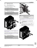
Check that, with the vacuum pump turned off, the target
vacuum is maintained for at least 1 hour.
3
Should you fail to reach the target vacuum within 2 hours or
maintain the vacuum for 1 hour, the system may contain too
much moisture. In that case, break the vacuum by pressurising
with nitrogen gas to a gauge pressure of 0.05 MPa (0.5 bar)
and repeat steps 1 to 3 until all moisture has been removed.
NOTICE
In case of 64BAW, perform the operations on
both units.
6.6.6
To insulate the refrigerant piping
After finishing the leak test and vacuum drying, the piping must be
insulated. Take into account the following points:
▪ Be sure to insulate the liquid and gas piping (for all units).
▪ Use heat resistant polyethylene foam which can withstand a
temperature of 70°C for liquid piping and polyethylene foam which
can withstand a temperature of 120°C for gas piping.
▪ Reinforce the insulation on the refrigerant piping according to the
installation environment.
Ambient
temperature
Humidity
Minimum thickness
≤30°C
75% to 80% RH
15 mm
>30°C
≥80% RH
20 mm
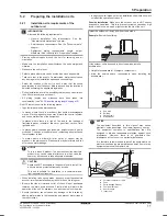
Condensation might form on the surface of the insulation.
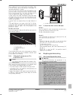
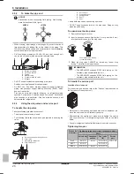
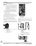
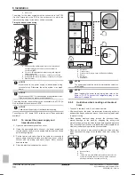
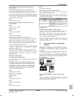
▪ If there is a possibility that condensation on the stop valve might
drip down into the indoor unit through gaps in the insulation and
piping because the outdoor unit is located higher than the indoor
unit, this must be prevented by sealing up the connections. See
below figure.
f
f
e
a
d
c
b
d
e
a
Gas line stop valve
b
Liquid line stop valve
c
Service port for adding refrigerant
d
Sealing up treatment
e
Insulation
f
Piping between indoor and outdoor unit
DANGER: RISK OF BURNING
Be sure to insulate local pipes, as touching them can
cause burns.
6.7
Charging refrigerant
6.7.1
About charging refrigerant
Once vacuum drying is finished, additional refrigerant charging can
start.
6.7.2
Precautions when charging refrigerant
INFORMATION
Also read the precautions and requirements in the
following chapters:
▪ General safety precautions
▪ Preparation
WARNING
▪ Only use R410A as refrigerant. Other substances may
cause explosions and accidents.
▪ R410A contains fluorinated greenhouse gases. Its
global warming potential (GWP) value is 2087.5. Do
NOT vent these gases into the atmosphere.
▪ When charging refrigerant, always use protective
gloves and safety glasses.
NOTICE
If the power of some units is turned off, the charging
procedure cannot be finished properly.
NOTICE
Be sure to turn on the power 6 hours before operation in
order to have power running to the crankcase heater and
to protect the compressor.
NOTICE
If operation is performed within 12 minutes after the indoor
and outdoor units are turned on, the H2P LED will be lit
and the compressor will not operate before communication
is established between outdoor unit(s) and indoor units.
NOTICE
Close the front panel before any refrigerant charge
operation is executed. Without the front panel attached the
unit cannot judge correctly whether it is operating properly
or not.
NOTICE
In case of maintenance and the system (outdoor unit+field
indoor units) does not contain any refrigerant any
more (e.g., after refrigerant reclaim operation), the unit has
to be charged with its original amount of refrigerant (refer
to the nameplate on the unit) by pre-charging before the
automatic charging function can be started.
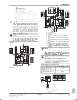
NOTICE
▪ The refrigerant charging port is connected to the piping
inside the unit. The unit's internal piping is already
factory charged with refrigerant, so be careful when
connecting the charge hose.
▪ After adding the refrigerant, do not forget to close the
lid of the refrigerant charging port. The tightening
torque for the lid is 11.5 to 13.9 N•m.
▪ In order to ensure uniform refrigerant distribution, it
may take the compressor ±10 minutes to start up after
the unit has started operation. This is not a malfunction.
6.7.3
To determine the additional refrigerant
amount
INFORMATION
For final charge adjustment in a test laboratory, contact
your dealer.
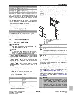
The additional refrigerant charge calculation is based on the liquid
piping size.
Formula:
R=(X
Ø9.52
×0.059)+(X
Ø12.7
×0.12)
R
Additional refrigerant to be charged [in kg and rounded off
to 1 decimal place]
X
1, 2
Total length [m] of liquid piping size at
Øa
Example
SEHVX64BAW (indoor unit) + 2× SERHQ032BAW1 (outdoor unit)
Содержание SERHQ020BAW1
Страница 68: ......
Страница 69: ......
Страница 70: ......
Страница 71: ......
Страница 72: ...4P508020 1B 2018 04 Copyright 2018 Daikin...