Outline of Control (Outdoor Unit) < Symbols using in this manual >
Si33-105
90
Function R407C PLUS Series Heat Recovery System
"
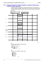
1
Compressor frequency
Fix the frequency at 41Hz + OFF + (OFF) for the basic operation.
However, increase the compressor operation step with 4-way valve function assuring control to
ensure the function of the 4-way valve.
"
2
Outdoor fan control
Regarding 24 to 34HP model, the fan (M12F) on the inverter box side stops if operating at fan
tap
or lower. Therefore, Tfin switches M12F to M11F.
"
3
Indoor unit instruction cancellation conditions
"
4
Indoor unit instruction cancellation conditions
"
5
Opening degree of Ev (in 3 compressor system: EV3) on sub unit side
20S2=ON
→
0pls
20S2=OFF
→
500pls
"
6
Indoor unit EV instruction
Instructed opening degree is shifted under the following conditions only on indoor unit with
cooling thermostat ON.
Th7-Te>40°C
→
1000pls
Th7-Te<15°C
→
200pls
∗∗∗∗
Initial status: 200pls
"
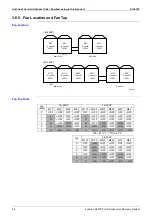
7
Indoor unit fan instruction
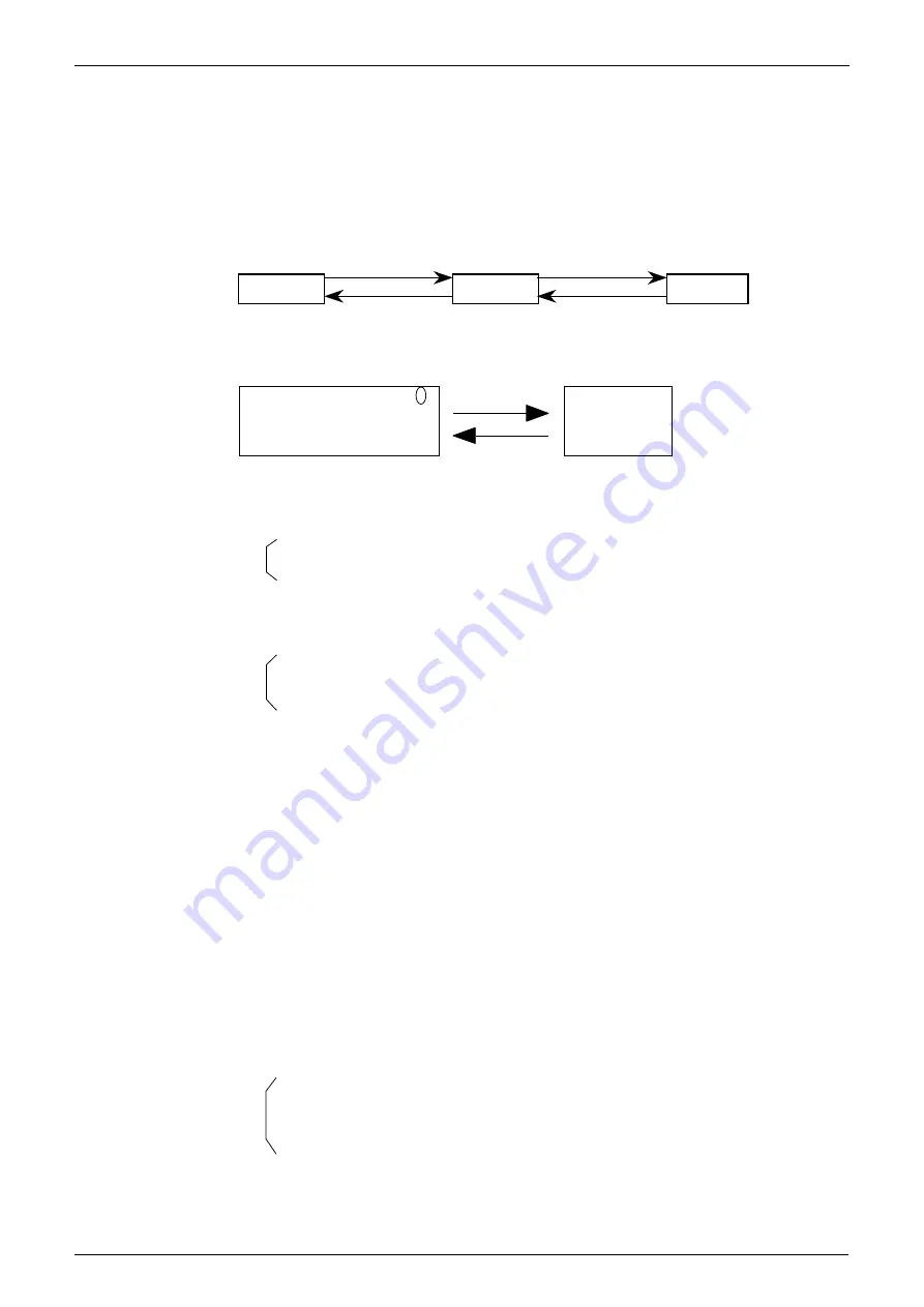
LL tap instruction is conducted after the startup control ending until the following conditions are
met.
Step
Step
Step 0
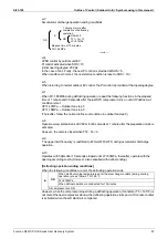
Pc>1.17
Pc<0.98MPa
Pc>0.78MPa
Pc<0.59MPa
(V2590)
M11F = H / L / OFF
M12F = OFF
0
M11F = OFF
M12F = ON
Tfin>87˚C
Tfin<67˚C
(V2591)
OR
HP>1.47MPa
Startup control ending
(V2592)
OR
DSH>30
Th7-Te>10
LP<0.1MPa
(V2593)
OR
HP>1.47MPa
Elapsed time of 4 minutes after startup control ending
Compressor stop
Activates during preparation of defrosting and oil return operation
(V2594)
Содержание R407C PLUS
Страница 1: ...System R407C PLUS Series Heat Recovery System Si33 105 Service Manual ...
Страница 11: ...Introduction Si33 105 x ...
Страница 41: ...Specifications Si33 105 30 Specifications R407C PLUS Series Heat Recovery System ...
Страница 147: ...Test Operation Si33 105 136 Test Operation R407C PLUS Series Heat Recovery System ...
Страница 158: ...Si33 105 Troubleshooting by Remote Controller Troubleshooting R407C PLUS Series Heat Recovery System 147 ...
Страница 160: ...Si33 105 Troubleshooting by Remote Controller Troubleshooting R407C PLUS Series Heat Recovery System 149 ...
Страница 229: ...Troubleshooting OP Unified ON OFF Controller Si33 105 218 Troubleshooting R407C PLUS Series Heat Recovery System ...
Страница 232: ...Si33 105 Piping Diagram Appendix R407C PLUS Series Heat Recovery System 221 RSEYP24 26 28 30KJY1 3D031938 ...
Страница 234: ...Si33 105 Piping Diagram Appendix R407C PLUS Series Heat Recovery System 223 BSVP250KJV1 4D014499A ...
Страница 237: ...Wiring Diagram Si33 105 226 Appendix R407C PLUS Series Heat Recovery System RSEYP24 26 28 30KJY1 3D031467 ...
Страница 238: ...Si33 105 Wiring Diagram Appendix R407C PLUS Series Heat Recovery System 227 2 2 BS Unit 3D014829B ...
Страница 240: ...Si33 105 Wiring Diagram Appendix R407C PLUS Series Heat Recovery System 229 FXYFP32 40 50 63 80 100 125KVE 3D020238B ...
Страница 241: ...Wiring Diagram Si33 105 230 Appendix R407C PLUS Series Heat Recovery System FXYCP20 25 32 63KV1 DU229 5139C ...
Страница 242: ...Si33 105 Wiring Diagram Appendix R407C PLUS Series Heat Recovery System 231 FXYCP40 50 80 125KV1 DU230 522C ...
Страница 243: ...Wiring Diagram Si33 105 232 Appendix R407C PLUS Series Heat Recovery System FXYKP25 32 40 63KV1 DU227 544C ...
Страница 244: ...Si33 105 Wiring Diagram Appendix R407C PLUS Series Heat Recovery System 233 FXYSP20 25 32 40 50 63KV1 DU227 545E ...
Страница 245: ...Wiring Diagram Si33 105 234 Appendix R407C PLUS Series Heat Recovery System FXYSP80 100 125KV1 DU230 519D ...
Страница 246: ...Si33 105 Wiring Diagram Appendix R407C PLUS Series Heat Recovery System 235 FXYMP40 50 63 80 100 125KV1 DU229 5140C ...
Страница 247: ...Wiring Diagram Si33 105 236 Appendix R407C PLUS Series Heat Recovery System FXYMP200 250KV1 3D011012B ...
Страница 248: ...Si33 105 Wiring Diagram Appendix R407C PLUS Series Heat Recovery System 237 FXYHP32 63 100KV1 DU228 531C ...
Страница 249: ...Wiring Diagram Si33 105 238 Appendix R407C PLUS Series Heat Recovery System FXYAP20 25 32 40 50 63KV1 DU221 561F ...
Страница 263: ...Si33 105 iv Index ...


