Si33-105
Specifications
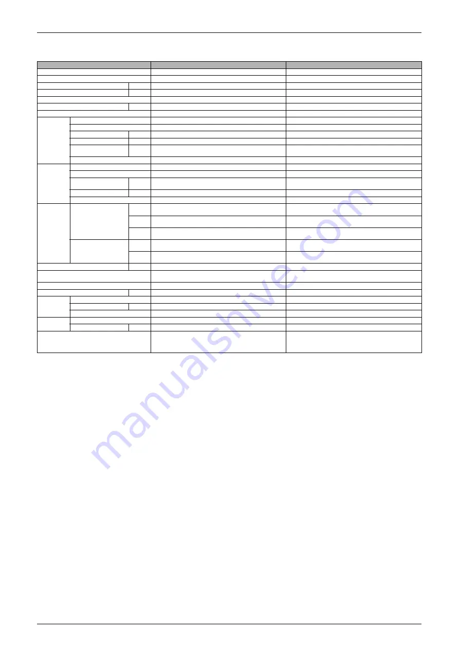
Specifications R407C PLUS Series Heat Recovery System
9
Notes:
"
1 Indoor temp. : 27°C DB or 19°C WB / outdoor temp. : 35°C DB / Equivalent piping length : 7.5m, level
difference : 0m.
"
2 Indoor temp. : 20°C DB / outdoor temp. : 7°C DB or 6°C WB / equivalent piping length : 7.5m, level
difference : 0m.
Model
RSEYP20KJY1
RSEYP24KJY1
Constituent Model (Main Unit + Sub Unit)
REYRXEP10KJY1
REYRXEP8KJY1
Power Supply
3 phase 50Hz 380-415V
3 phase 50Hz 380-415V
"
1 Cooling Capacity
kW
54.7
65.7
"
2 Heating Capacity
kW
54.7
65.7
Casing Color
Ivory white (5Y7.5/1)
Ivory white (5Y7.5/1)
Dimensions : (H×W×D)
mm
(1,440×1,280×690)+(1,440×1,280×690)
(1,460×2,580×690)+(1,220×1,280×690)
Heat Exchanger
Cross fin coil
Cross fin coil
Compressor
Model
JT236DCVTYE@2+JT265DATYE@2
JT236DCVTYE@2+JT300DATYE@2×2
Type
Hermetically sealed scroll type
Hermetically sealed scroll type
Piston Displacement
m³/h
(43.3+25.2)
(43.3+28.4+28.4)
Number of Revolutions
rpm
(5,510, 2,900)
(5,510, 2,900, 2,900)
Motor Output × Number
of Units
kW
5.5+7.5
5.5+7.5+7.5
Starting Method
Direct on line
Direct on line
Fan
Model
P52H11S
P52H11S
Type
Propellor fan
Propellor fan
Motor Output × Number
of Units
kW
(0.14+0.23)+(0.14+0.23)
(0.14+0.23)×2+(0.14+0.23)
Air Flow Rate
m³/min
340
490
Drive
Direct drive
Direct drive
Connecting
Pipes
Outdoor Unit
Liquid
pipe
φ
19.1 C1220T (Flare connection)
φ
19.1 C1220T (Flare connection)
Gas
pipe
φ
34.9 C1220T (Brazing connection)
φ
41.3 C1220T (Brazing connection)
Discharge
Pipe
φ
28.6 C1220T (Brazing connection)
φ
28.6 C1220T (Brazing connection)
Main Unit ~ Sub Unit
Liquid
pipe
φ
12.7 C1220T (Flare-Brazing connection)
φ
12.7 C1220T (Flare-Brazing connection)
Gas
pipe
φ
28.6 C1220T (Brazing-Brazing connection)
φ
28.6 C1220T (Brazing-Brazing connection)
Weight
kg
375+105
640+95
Safety Devices
High pressure switch, fan motor safety thermostat, inverter
overload protector, overcurrent relay, fusible plugs
High pressure switch, fan motor safety thermostat, inverter
overload protector, overcurrent relay, fusible plugs
Defrost Method
Deicer
Deicer
Capacity Control
%
11 ~ 100
11 ~ 100
Refrigerant
Refrigerant Name
R407C
R407C
Charge
kg
19.8
29.5
Control
Electronic expansion valve
Electronic expansion valve
Refrigerator
Oil
Refrigerant Oil
DAPHNE FVC68D
DAPHNE FVC68D
Charge Volume
L
4.0+4.0
4.0+4.0+4.0
Standard Accessories
Accessories pipe (Gas, liquid and Discharge pipe),
Connection pipes (Gas pipe), Installation manual,
Operation manual, Jumper wire (Low, High voltage),
Clamps
Accessories pipe (Gas, liquid and Discharge pipe),
Connection pipes (Gas pipe), Installation manual,
Operation manual, Jumper wire (Low, High voltage),
Clamps
Содержание R407C PLUS
Страница 1: ...System R407C PLUS Series Heat Recovery System Si33 105 Service Manual ...
Страница 11: ...Introduction Si33 105 x ...
Страница 41: ...Specifications Si33 105 30 Specifications R407C PLUS Series Heat Recovery System ...
Страница 147: ...Test Operation Si33 105 136 Test Operation R407C PLUS Series Heat Recovery System ...
Страница 158: ...Si33 105 Troubleshooting by Remote Controller Troubleshooting R407C PLUS Series Heat Recovery System 147 ...
Страница 160: ...Si33 105 Troubleshooting by Remote Controller Troubleshooting R407C PLUS Series Heat Recovery System 149 ...
Страница 229: ...Troubleshooting OP Unified ON OFF Controller Si33 105 218 Troubleshooting R407C PLUS Series Heat Recovery System ...
Страница 232: ...Si33 105 Piping Diagram Appendix R407C PLUS Series Heat Recovery System 221 RSEYP24 26 28 30KJY1 3D031938 ...
Страница 234: ...Si33 105 Piping Diagram Appendix R407C PLUS Series Heat Recovery System 223 BSVP250KJV1 4D014499A ...
Страница 237: ...Wiring Diagram Si33 105 226 Appendix R407C PLUS Series Heat Recovery System RSEYP24 26 28 30KJY1 3D031467 ...
Страница 238: ...Si33 105 Wiring Diagram Appendix R407C PLUS Series Heat Recovery System 227 2 2 BS Unit 3D014829B ...
Страница 240: ...Si33 105 Wiring Diagram Appendix R407C PLUS Series Heat Recovery System 229 FXYFP32 40 50 63 80 100 125KVE 3D020238B ...
Страница 241: ...Wiring Diagram Si33 105 230 Appendix R407C PLUS Series Heat Recovery System FXYCP20 25 32 63KV1 DU229 5139C ...
Страница 242: ...Si33 105 Wiring Diagram Appendix R407C PLUS Series Heat Recovery System 231 FXYCP40 50 80 125KV1 DU230 522C ...
Страница 243: ...Wiring Diagram Si33 105 232 Appendix R407C PLUS Series Heat Recovery System FXYKP25 32 40 63KV1 DU227 544C ...
Страница 244: ...Si33 105 Wiring Diagram Appendix R407C PLUS Series Heat Recovery System 233 FXYSP20 25 32 40 50 63KV1 DU227 545E ...
Страница 245: ...Wiring Diagram Si33 105 234 Appendix R407C PLUS Series Heat Recovery System FXYSP80 100 125KV1 DU230 519D ...
Страница 246: ...Si33 105 Wiring Diagram Appendix R407C PLUS Series Heat Recovery System 235 FXYMP40 50 63 80 100 125KV1 DU229 5140C ...
Страница 247: ...Wiring Diagram Si33 105 236 Appendix R407C PLUS Series Heat Recovery System FXYMP200 250KV1 3D011012B ...
Страница 248: ...Si33 105 Wiring Diagram Appendix R407C PLUS Series Heat Recovery System 237 FXYHP32 63 100KV1 DU228 531C ...
Страница 249: ...Wiring Diagram Si33 105 238 Appendix R407C PLUS Series Heat Recovery System FXYAP20 25 32 40 50 63KV1 DU221 561F ...
Страница 263: ...Si33 105 iv Index ...


