Specifications
Si33-105
20
Specifications R407C PLUS Series Heat Recovery System
Ceiling Mounted Built-in Type
Notes:
"
1 Nominal cooling capacities are based on the following conditions:
Return air temperature : 27°C DB, 19°C WB, Outdoor temperature : 35°C DB
Equivalent ref. piping : 5m (Horizontal)
"
2 Nominal heating capacities are based on the following conditions:
Return air temperature : 20°C DB, Outdoor temperature : 7°C DB, 6°C WB
Equivalent ref. piping : 5m (Horizontal)
"
3 Capacities are net, including a deduction for cooling (an addition for heating) for indoor fan motor heat.
"
4 Static external pressure is changeable to change over the connectors inside electrical box, this pressure
means “High static pressure-Standard”.
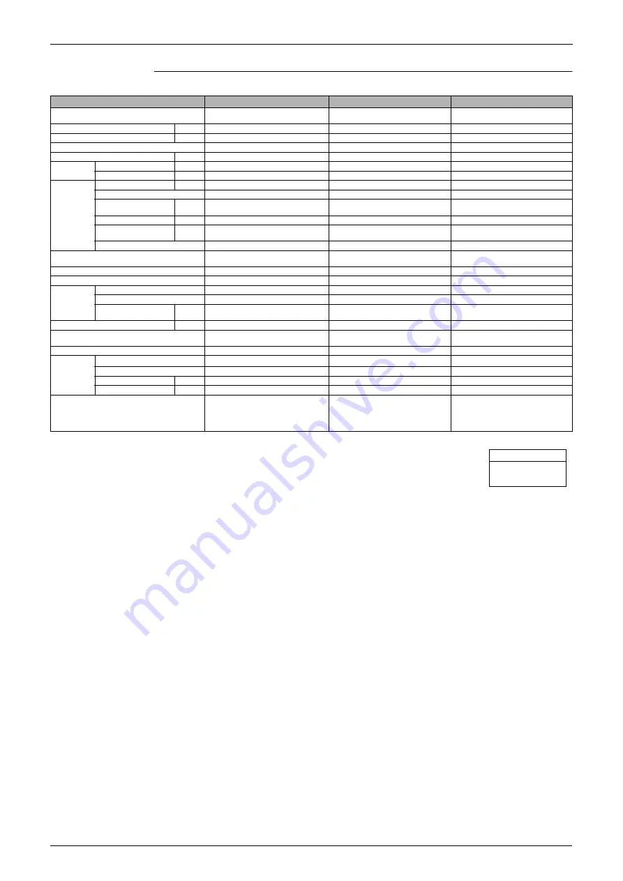
Model
FXYSP80KV1
FXYSP100KV1
FXYSP125KV1
Power Supply
1 phase 50Hz
220-240V
1 phase 50Hz
220-240V
1 phase 50Hz
220-240V
"
"
"
"
1 Cooling Capacity
kW
9.0
11.2
14.0
"
"
"
"
2 Heating Capacity
kW
10.0
12.5
16.0
Casing
Galvanized Steel Plate
Galvanized Steel Plate
Galvanized Steel Plate
Dimensions: (H×W×D)
mm
300×1,400×800
300×1,400×800
300×1,400×800
Coil (Cross
Fin Coil)
Rows×Stages×Fin Pitch
mm
3×14×1.75
3×14×1.75
3×14×1.75
Face Area
m²
0.338
0.338
0.338
Fan
Model
V1
3D18H2AH1V1
3D18H2AH1V1
3D18H2AG1V1
Type
Sirocco Fan
Sirocco Fan
Sirocco Fan
Motor Output × Number
of Units
W
135×1
135×1
225×1
Air Flow Rate (H/L)
m³/min
27/20
28/20.5
38/28
"
"
"
"
4 External Static
Pressure
Pa
88-49
98-69
78-39
Drive
Direct Drive
Direct Drive
Direct Drive
Temperature Control
Microprocessor Thermostat for
Cooling and Heating
Microprocessor Thermostat for
Cooling and Heating
Microprocessor Thermostat for
Cooling and Heating
Sound Absorbing Thermal Insulation Material
Glass Fiber
Glass Fiber
Glass Fiber
Air Filter
Resin Net (with Mold Resistant)
Resin Net (with Mold Resistant)
Resin Net (with Mold Resistant)
Piping
Connections
Liquid Pipes
9.5mm (Flare Connection)
9.5mm (Flare Connection)
9.5mm (Flare Connection)
Gas Pipes
15.9mm (Flare Connection)
19.1mm (Flare Connection)
19.1mm (Flare Connection)
Drain Pipe
(mm)
VP25 (External Dia. 32
Internal Dia. 25)
VP25 (External Dia. 32
Internal Dia. 25)
VP25 (External Dia. 32
Internal Dia. 25)
Weight
kg
51
51
52
Safety Devices
Fuse
Thermal Protector for Fan Motor
Fuse
Thermal Protector for Fan Motor
Fuse
Thermal Protector for Fan Motor
Refrigerant Control
Electronic Expansion Valve
Electronic Expansion Valve
Electronic Expansion Valve
Decoration
Panels
Model
BYBS125DJW1
BYBS125DJW1
BYBS125DJW1
Panel Color
White (10Y9/0.5)
White (10Y9/0.5)
White (10Y9/0.5)
Dimensions: (H×W×D)
mm
55×1,500×500
55×1,500×500
55×1,500×500
Weight
kg
6.5
6.5
6.5
Standard Accessories
Operation Manual, Installation Manual,
Paper Pattern for Installation, Drain
Hose, Clamp Metal, Insulation for
Fitting, Sealing Pads, Clamps, Screws,
Washers.
Operation Manual, Installation
Manual, Paper Pattern for Installation,
Drain Hose, Clamp Metal, Insulation
for Fitting, Sealing Pads, Clamps,
Screws, Washers.
Operation Manual, Installation
Manual, Paper Pattern for Installation,
Drain Hose, Clamp Metal, Insulation
for Fitting, Sealing Pads, Clamps,
Screws, Washers.
Conversion Formulae
kcal/h=kW×860
Btu/h=kW×3414
cfm=m³/min×35.3
Содержание R407C PLUS
Страница 1: ...System R407C PLUS Series Heat Recovery System Si33 105 Service Manual ...
Страница 11: ...Introduction Si33 105 x ...
Страница 41: ...Specifications Si33 105 30 Specifications R407C PLUS Series Heat Recovery System ...
Страница 147: ...Test Operation Si33 105 136 Test Operation R407C PLUS Series Heat Recovery System ...
Страница 158: ...Si33 105 Troubleshooting by Remote Controller Troubleshooting R407C PLUS Series Heat Recovery System 147 ...
Страница 160: ...Si33 105 Troubleshooting by Remote Controller Troubleshooting R407C PLUS Series Heat Recovery System 149 ...
Страница 229: ...Troubleshooting OP Unified ON OFF Controller Si33 105 218 Troubleshooting R407C PLUS Series Heat Recovery System ...
Страница 232: ...Si33 105 Piping Diagram Appendix R407C PLUS Series Heat Recovery System 221 RSEYP24 26 28 30KJY1 3D031938 ...
Страница 234: ...Si33 105 Piping Diagram Appendix R407C PLUS Series Heat Recovery System 223 BSVP250KJV1 4D014499A ...
Страница 237: ...Wiring Diagram Si33 105 226 Appendix R407C PLUS Series Heat Recovery System RSEYP24 26 28 30KJY1 3D031467 ...
Страница 238: ...Si33 105 Wiring Diagram Appendix R407C PLUS Series Heat Recovery System 227 2 2 BS Unit 3D014829B ...
Страница 240: ...Si33 105 Wiring Diagram Appendix R407C PLUS Series Heat Recovery System 229 FXYFP32 40 50 63 80 100 125KVE 3D020238B ...
Страница 241: ...Wiring Diagram Si33 105 230 Appendix R407C PLUS Series Heat Recovery System FXYCP20 25 32 63KV1 DU229 5139C ...
Страница 242: ...Si33 105 Wiring Diagram Appendix R407C PLUS Series Heat Recovery System 231 FXYCP40 50 80 125KV1 DU230 522C ...
Страница 243: ...Wiring Diagram Si33 105 232 Appendix R407C PLUS Series Heat Recovery System FXYKP25 32 40 63KV1 DU227 544C ...
Страница 244: ...Si33 105 Wiring Diagram Appendix R407C PLUS Series Heat Recovery System 233 FXYSP20 25 32 40 50 63KV1 DU227 545E ...
Страница 245: ...Wiring Diagram Si33 105 234 Appendix R407C PLUS Series Heat Recovery System FXYSP80 100 125KV1 DU230 519D ...
Страница 246: ...Si33 105 Wiring Diagram Appendix R407C PLUS Series Heat Recovery System 235 FXYMP40 50 63 80 100 125KV1 DU229 5140C ...
Страница 247: ...Wiring Diagram Si33 105 236 Appendix R407C PLUS Series Heat Recovery System FXYMP200 250KV1 3D011012B ...
Страница 248: ...Si33 105 Wiring Diagram Appendix R407C PLUS Series Heat Recovery System 237 FXYHP32 63 100KV1 DU228 531C ...
Страница 249: ...Wiring Diagram Si33 105 238 Appendix R407C PLUS Series Heat Recovery System FXYAP20 25 32 40 50 63KV1 DU221 561F ...
Страница 263: ...Si33 105 iv Index ...


