manualshive.com logo in svg
background image

16

defrost control board.

2. 

Remove jumper from timer pins and jump across test 

pins on defrost control board.


NOTE:

 Do not use screwdriver or field


supplied jumper to test the control.

3.  Set thermostat to call for heating. System should go 

into defrost within 21 seconds.

4.  Immediately remove jumper from test pins.

5.  Using VOM check for voltage across terminals “C & 

O”. Meter should read 24 volts.

6.  Using VOM check for voltage across fan terminals 

DF1 and DF2 on the board. Should read line voltage 

(208-230 VAC) indicating the relay is open in the 

defrost mode.

7.  Using VOM check for voltage across “W”/”W2” & “C” 

terminals on the board. Should read 24 volts.

8.  If not as above, replace control board.

9.  Set thermostat to off position and disconnect power. 

Remove jumper from defrost thermostat and replace 

timer jumper to the desired defrost time.

NOTE: Remove jumper across defrost thermostat 

before returning system to service. 

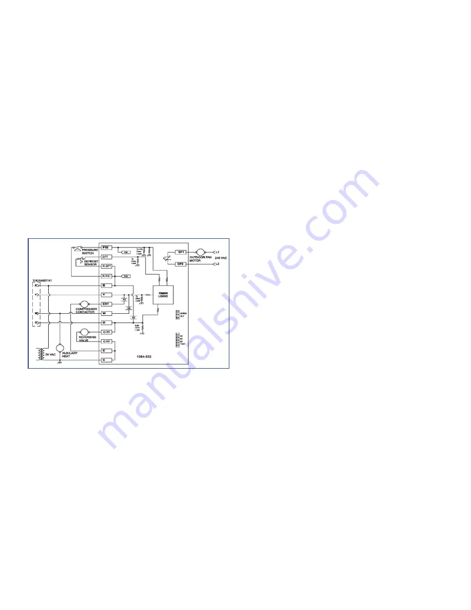
Defrost Control Wiring Schematic

Testing Defrost Thermostat

1. 

Install a thermocouple type temperature test lead on 

the tube adjacent to the defrost control. Insulate the 

lead point of contact.

2.  Check the temperature at which the control closes its 

contacts by lowering the temperature of the control. 

It should close at approximately 30°F.

3.  Check the temperature at which the control opens its 

contacts by raising the temperature of the control. It 

should open at approximately 60°F.  

4.  If not as above, replace control.

REVERSING VALVE TROUBLESHOOTING

Checking Reversing Valve and Solenoid

Reversing valve used in heat pumps could potentially leak 

internally. Discharge gases can leak into the suction inside 

the valve. Compound gages will give the same symptoms 

as bad compressor valves or broken scroll flanks. The 

temperature between true suction and the suction line after 

the valve should not be greater than 4 degrees. Note: The 

center tube is always the suction line and should be cold.

Troubleshooting the Reversing Valve for 

Electrical Failure

1.  Place unit into the cooling mode. Test for 24 volts at 

the solenoid. If there is no voltage present at coil, 

check the control voltage. 

2. 

If voltage is present, loosen the nut on the top of 

the coil. Remove the coil, there should be slight 

resistance. 

3.  If the slight resistance is felt, remove the coil. As 

you remove the coil listen carefully, an audible 

click should be detected. The clicking is due to the 

movement of the pilot valve plunger. The absence of 

a clicking sound indicates the plunger is stuck. 

Troubleshooting Mechanical Failures on a 

Reversing Valve by Pressure

1. 

Troubleshooting the reversing valve can be done by 

pressure and touch. 

2.  Raise the head pressure. In the cooling mode block 

the fan exhaust. Once head pressure has been 

raised, cycle between cooling and heating and see if 

the piston can be freed. 

Troubleshooting Mechanical Failures on a 

Reversing Valve byTemperature

1.  When operating properly the valve contains 

refrigerant gases at certain temperatures. 

2. 

The discharge line should be the same temperature 

after the valves discharge line. 

3. 

The true suction should be the same as the suction 

line after the valve. If there is a 4-degree difference, 

valve is leaking 

When stuck in the mid-position, part of the discharge gas 

from the compressor is directed back to the suction side, 

resulting in excessively high suction pressure. An increase 

in the suction line temperature through the reversing 

valve can also be measured. Check operation of the valve 

by starting the system and switching the operation from 

COOLING to HEATING cycle. 

If the valve fails to change its position, test the voltage 

(24V) at the valve coil terminals, while the system is on the 

COOLING cycle.

If voltage is registered at the coil, tap the valve body lightly 

while switching the system from HEATING to COOLING, 

etc. If this fails to cause the valve to switch positions, 

remove the coil connector cap and test the continuity of 

the reversing valve solenoid coil. If the coil does not test 

continuous - replace it. If the coil test continuous and 24 

volts is present at the coil terminals, the valve is inoperative 

- replace it.

Содержание M Series

Страница 1: ...N THIS MANUAL SHOULD SERVICE THE EQUIPMENT THE MANUFACTURER WILL NOT BE RESPONSIBLE FOR ANY INJURY OR PROPERTY DAMAGE ARISING FROM IMPROPER SERVICE OR SERVICE PROCEDURES IF YOU SERVICE THIS UNIT YOU A...

Страница 2: ...MENT PARTS Ordering Parts When reporting shortages or damages or ordering repair parts give the complete unit model and serial numbers as stamped on the unit s nameplate Replacement parts for this app...

Страница 3: ...ng or installing this unit Multiple power sources may be present Failure to do so may cause property damage personal injury or death WARNING To prevent the risk of property damage personal injury or d...

Страница 4: ...ly within 5 days 4 File the claim with the following supporting documents a Original Bill of Lading certified copy or indemnity bond b Original paid freight bill or indemnity in lieu thereof c Origina...

Страница 5: ...ses have holes under the outdoor coil to permit drainage of defrost water accumulation The unit must be situated to permit free unobstructed drainage of the defrost water and ice A minimum of 2 cleara...

Страница 6: ...36 minimum clearance is required between the condenser coils Adequate clearance around the unit should be kept for safety service maintenance and proper unit operation A clearance of 48 is recommende...

Страница 7: ...bserved when installing the unit Provisions for forks have been included in the unit base frame No other fork locations are approved Unit must be lifted by the four lifting holes located at the base f...

Страница 8: ...is unit Multiple power sources may be present Failure to do so may cause property damage personal injury or death WARNING HIGH VOLTAGE To avoid personal injury or death due to electrical shock do not...

Страница 9: ...t the power leads at the point of distribution in accordance with the unit data plate The unit must be electrically grounded in accordance with local codes or in the absence of local codes with the la...

Страница 10: ...ever connecting thermostat wires to terminals on sub base DO NOT use larger than 18 AWG wire A transition to 18 AWG wire may be required before entering thermostat sub base NOTE Refer to unit wiring d...

Страница 11: ...must first be performed in accordance with this manual Damage or repairs due to failure to comply with these requirements are not covered under the warranty After the machines are used for temporary h...

Страница 12: ...airflow setting to be between 300 and 500 CFM per ton see Table below For models with electric heat the total airflow must not be less than that required for operation of the electric heaters See App...

Страница 13: ...quid small line near liquid line access fitting with adequate contact and insulate for best possible reading 3 Check subcooling and superheat System should have a subcooling and superheat within the r...

Страница 14: ...operation if outdoor ambient is mild If the outdoor ambient is low and the unit operates properly in the heating cycle you may check the pressure cutout operation by blocking off the indoor return air...

Страница 15: ...surfaces of the outdoor coil under certain weather conditions of temperature and relative humidity Therefore it is necessary to reverse the flow of the refrigerant to provide hot gas in the outdoor co...

Страница 16: ...for Electrical Failure 1 Place unit into the cooling mode Test for 24 volts at the solenoid If there is no voltage present at coil check the control voltage 2 If voltage is present loosen the nut on...

Страница 17: ...be made at least every two months more often if necessary because of local conditions and usage Dirty throwaway filters should be discarded and replaced with a new clean filter Disposable return air f...

Страница 18: ...18 Wiring Example Electric Heat Wiring Example...

Страница 19: ...2080 939 0 74 0 4 2056 952 0 75 0 6 1973 1000 0 79 0 6 1967 1003 0 79 0 8 1887 1048 0 83 0 8 1890 1051 0 83 T3 0 2 2176 878 0 69 T3 0 2 2145 902 0 71 0 4 2080 939 0 74 0 4 2056 952 0 75 0 6 1973 1000...

Страница 20: ...2 6 5 119 129 125 150 134 148 150 150 7 2 6 5 142 155 150 175 6 9 1 0 3 3 5 Direct Drive Standard Static 1 GPH1660M 208 230 1 60 1 26 9 152 9 EH 1S15 11 3 15 0 54 2 62 5 EH 1S20 15 0 20 0 72 2 83 3 EH...

Страница 21: ...RB LOCATION EMBOSS FOR THRU THE BASE UTILITIES RETURN 11 X 25 SUPPLY 12 X 17 Horizontal Discharge Vertical Discharge NOTE Refer to IOD 7082 included in the literature pack for installing horizontal du...

Страница 22: ...lectric Heater Heater Type X Staged S SCR modulating Voltage 1 208 230 1 60 Single phase 60 Hz Chassis S Small Kilowatt 5 5 kW 10 10 kW 15 15 kW 18 18 KW 20 20 kW 30 30 kW EH S05 5 1500 EH S10 10 1500...

Страница 23: ...1 F1 BK RD 208 230V 1PH 60Hz L1 L2 T1 T2 C S CM BR RD GR BK GR RD FB3 F3 F3 5 BK RD RD YL BR BK PU BK RD PU BK 5 L1 L2 T1 T2 BK BC COMP RC COM H F PU PU CMC L1 L2 T1 T2 FB2 F2 F2 BK RD BK RD BK PU BR...

Страница 24: ...LP Liquid Propane Residential Package Outdoor Section ELECTRICAL Supply Voltage Measure L1 and L2 Voltage L1 L2 Compressor Amps Condenser Fan Amps PRESSURES TEMPERATURES Suction Circuit Pressure Suct...

Страница 25: ...25 THIS PAGE INTENTIONALLY LEFT BLANK...

Страница 26: ...26 THIS PAGE INTENTIONALLY LEFT BLANK...

Страница 27: ...27 THIS PAGE INTENTIONALLY LEFT BLANK...

Страница 28: ...OODMAN BRAND AMANA BRAND GOODMAN BRAND AMANA BRAND PRODUCT REGISTRATION Thank you for your recent purchase Though not required to get the protection of the standard warranty registering your product i...

Отзывы: