


12
Nameplate Voltage -
That voltage assigned to a piece of
equipment for the purpose of designating its voltage class
and for the purpose of defining the minimum and maximum
voltage at which the equipment will operate.
Utilization Voltage -
The voltage of the line terminals
of the equipment at which the equipment must give fully
satisfactory performance. Once it is established that supply
voltage will be maintained within the utilization range under
all system conditions, check and calculate if an unbalanced
condition exists between phases. Calculate percent voltage
unbalance as follows:
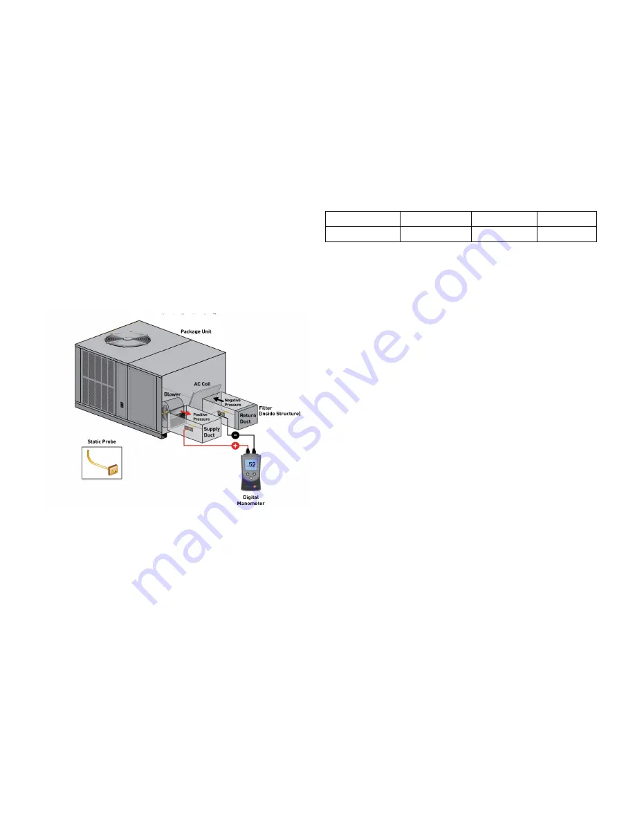
TOTAL EXTERNAL STATIC PRESSURE
CHECK
The total external static pressure must be checked on this
unit to determine if the airflow is proper.
Total External Static Testing
1.
Using a digital manometer measure the static
pressure of the return duct at the inlet of the unit
(Negative Pressure).
Total External Static
2.
Measure the static pressure of the supply duct
(Positive Pressure).
3. Add the two readings together
NOTE: Both readings may be taken simultaneously
and read directly on the manometer if so desired.
4. Consult proper table for quantity of air.
If the external static pressure exceeds the minimum or
maximum allowable statics, check for closed dampers, dirty
filter, undersized or poorly laid out ductwork.
AIR FLOW ADJUSTMENTS
When the final adjustments are complete, the current
draw of the motor should be checked and compared to
the full load current rating of the motor. The amperage
must not exceed the service factor stamped on the motor
nameplate.
If an economizer is installed, check the unit operating
balance with the economizer at full outside air and at
minimum outside air.
High stage airflow setting to be between 300 and 500
CFM per ton, see Table below. For models with electric
heat the total airflow must not be less than that required
for operation of the electric heaters. See Appendix D for
minimum airflow for specific electric heaters.
NOTE: Never run CFM below 300 CFM per ton,
evaporator freezing or poor unit performance is
possible.
Model
Minimum
Maximum
GPHM56041
1500
1850
2500
Nominal
High Stage Airflow Setting, CFM
(without electric heat)
EEM - Standard Static Drive Motor
Adjust the CFM for the unit by changing the position of
the low voltage leads on the terminal block TB1. Refer to
Appendix A for blower performance at each speed tap
NOTE: If more than one lead is energized
simultaneously, the motor will run at the higher
speed.
Fan speed for G (Fan), Y1 (Low Cool) and W1 (Low Heat)
are fixed setting on TB1/T1 and cannot be moved.
Purple wire Y2 (High Cool) and Brown wire W2 (High Heat)
are connected to TB1/T2. These wires can be moved
together or separately and placed on any unoccupied
terminal T3-T5.
Note: for proper operation Y2 and W2 should have a higher
speed setting than the G, Y1 and W1 speed setting.
If Electric Heater kit is installed use the red wire provided
with the literature kit to jumper terminal TB1/W1 to an
unoccupied speed tap that satisfies the minimum airflow
required for the heater kit. This must be a different tap
than Y2 is connected to. Refer to Appendix D for minimum
required airflow for electric heaters.
Note: On Heat Pump units, the Yellow (YL) wire
from relay BR1 to TB1/T2 must always be moved
to the same terminal location as the Brown (BR)
wire after adjustments are made, to ensure
proper blower speed during defrost operation.
SUPERHEAT AND SUBCOOLING
Checking Subcooling
NOTE: Units with a TXV should be charged to
Subcooling only.
EXAMPLE:
a. Liquid Line Pressure = 417 PSI
b. Corresponding Temp. = 120°F
c. Thermometer on Liquid line = 109°F.
Содержание M Series
Страница 18: ...18 Wiring Example Electric Heat Wiring Example...
Страница 25: ...25 THIS PAGE INTENTIONALLY LEFT BLANK...
Страница 26: ...26 THIS PAGE INTENTIONALLY LEFT BLANK...
Страница 27: ...27 THIS PAGE INTENTIONALLY LEFT BLANK...


