D-EIMWC00208-16EN - 19/48
Unit limitation Electrical wiring (Optional)
The machine’s microprocessor allows to limit the capacity by means of two separate criteria:
>Load limitation: The load can be varied by means of a 420 mA external signal from a BMS.
The signal cable must be directly connected to terminals 36 and 37 of the M3 terminal board.
The signal cable must be of the shielded type and must not be laid in the vicinity of the power cables, so as not
to induce interference with the electronic controller.
-
Current limitation: The machine’s load can be varied by means of a 420 mA external signal from an external
device. In this case, current control limits must be set on the microprocessor so that the microprocessor
transmits the value of the measured current and limits it.
The signal cable must be directly connected to terminals 36 and 37 of the M3 terminal board.
The signal cable must be of the shielded type and must not be laid in the vicinity of the power cables, so as not
to induce interference with the electronic controller.
A digital input allows to enable the current limitation at the desired time. Connect the enabling switch or the
timer (clean contact) to terminals 5 and 9.
Attention: the two options cannot be enabled simultaneously. Setting one function excludes the other.
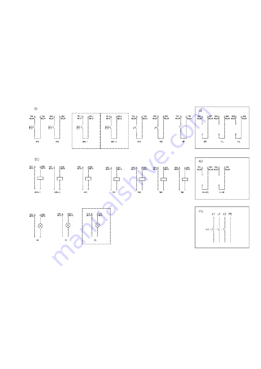
Fig. 9 - User connection to the interface terminal board
LEGEND
1S
Compressor Status 1
PS
Power Supply
2S
Compressor Status 2
Q10
Main Switch
Al
Analog Inputs
S.O. Setpoint Override
AO
Analog Output
TW 1
Tower 1 Fan Step
C-3W
Condenser 3-W ay Valve
TW 2
Tower 2 Fan Step
C.L.
Current Limit
TW 3
Tower 3 Fan Step
CFS
Condensator Flow Switch
TW 4
Tower 4 Fan Step
CLE
Current Limit Enable
CP-VFD
Condenser Pump VFD
D.L.
Demand Limit
DI
Digital Inputs
DO
Digital Outputs
DPS
Double Set Point
EF
Esternal Fault
EFS
Evaporator Flow Switch
EFS-1
Evaporator Flow Switch 1
EFS-2
Evaporator Flow Switch 2
GA
General Alarm
KPC
Condensator Water Pump
KPE-1
Evaporator Water Pump 1
KPE-2
Evaporator Water Pump 2
Содержание EWLD160~550G-SS
Страница 14: ...D EIMWC00208 16EN 14 48 Fig 7 Condenser Located above Chiller Unit Fig 8 Condenser Located below Chiller Unit...
Страница 21: ...D EIMWC00208 16EN 21 48 Fig 10 Refrigeration cycle EWWD G SS EWWD G XS 23 5 bar...
Страница 22: ...D EIMWC00208 16EN 22 48 Fig 11 Refrigeration cycle EWWD G SS EWWD G XS Partial Heat recovery 23 5 bar...
Страница 23: ...D EIMWC00208 16EN 23 48 Fig 12 Refrigeration cycle EWLD G SS OPTIONAL 23 5 bar...
Страница 45: ...D EIMWC00208 16EN 45 48...
Страница 46: ...D EIMWC00208 16EN 46 48...
Страница 47: ...D EIMWC00208 16EN 47 48...


