EHVH/X16
Daikin Altherma - Low Temperature Split
4P313777-1 – 2012.05
Installer reference guide
18
6 Preparation
6
Preparation
6.1
Preparing installation site
Do NOT install the unit in places often used as work place. In case of
construction works (e.g. grinding works) where a lot of dust is
created, the unit must be covered.
Choose the installation location with sufficient place for carrying the
unit in and out of the site.
6.1.1 Installation site requirements of the indoor
unit
Q
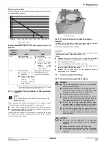
Mind the measurement guidelines:
Q
Mind the following spacing installation guidelines:
Do NOT install the unit in places such as:
Q
Where there is mist of mineral oil, oil spray or vapour.
Plastic parts may deteriorate, and cause them to fall out or water
to leak.
Q
Do NOT install the unit in sound sensitive areas (e.g. near a
bedroom and the like), so that the operation noise will cause no
trouble.
Note: If the sound is measured under actual installation
conditions, the measured value will be higher than the sound
pressure level mentioned in Sound spectrum due to
environmental noise and sound reflections.
Q
The foundation must be strong enough to bear the weight of the
unit. Take the weight of the unit with a domestic hot water tank
full of water into account.
Make sure, in the event of a water leak, water cannot cause any
damage to the installation space and surroundings.
Q
In places with high humidity (max. RH=85%), for example a
bathroom.
Q
In places where frost is possible. Ambient temperature around
the indoor unit should be >5°C.
Q
The indoor unit is designed for indoor installation only and for
ambient temperatures ranging 5~35°C in cooling mode and
5~30°C in heating mode.
6.2
Preparing water piping
6.2.1 Water circuit requirements
Q
Use the indoor unit only in a closed water system.
Using the system in an open water system will lead to excessive
corrosion.
Q
The maximum water pressure is 4 bar.
Provide adequate safeguards in the water circuit to ensure that
the maximum pressure is NOT exceeded.
Q
All installed piping and piping accessories (valve,
connections,…) must withstand the following temperatures:
Q
Make all water piping connections in accordance with the
applicable legislation and the outlook diagram that is delivered
with the unit, respecting the water inlet and outlet.
Q
Do NOT use excessive force when connecting the piping.
Deformation of the piping can cause malfunctioning of the unit.
Q
Provide drain taps at all low points of the system in order to allow
complete drainage of the water circuit.
Q
Provide a proper drain for the pressure relief valve to avoid
water dripping out of the unit. See "7.3.2 To connect the
pressure relief valve to the drain" on page 23.
Q
Provide air vents at all high points of the system, which must
also be easily accessible for servicing. An automatic air purge is
provided in the indoor unit. Check that the air purge is NOT
tightened too much, so that automatic release of air in the water
circuit is possible.
Maximum refrigerant piping length between indoor
unit and outdoor unit
75 m
(a)
Minimum refrigerant piping length between indoor
unit and outdoor unit
3 m
(b)
Maximum height difference between indoor unit and
outdoor unit
30 m
(a)
Check the outdoor unit installation manual.
(b)
When <5 m, you need to recharge the outdoor unit (check the
outdoor unit installation manual).
>500
>10
>10
(mm)
INFORMATION
The following illustration is an example and may NOT
match your system layout.
a
Outdoor unit
b
Indoor unit
c
Heat exchanger
d
Backup heater
e
Pump
f
Stop valve
g
Motorised 3-way valve
h
Motorised 2-way valve (field supply)
i
Collector
j
Domestic hot water tank
k
Heat exchanger coil
FCU1...3
Fan coil unit (optional)
FHL1...3
Floor heating loop
M
M
FCU1
FCU2
FCU3
FHL1
FHL2
FHL3
a
b
c
d
e
f
g
f
h
i
i
i
i
j
k
65°C
65°C
Содержание EHVH16S18CA
Страница 84: ...4P313777 1 2012 05 Copyright 2012 Daikin ...


