


39
A ComfortNet heating/air conditioning system differs from
a non-communicating/traditional system in the manner in
which the indoor unit, outdoor unit and thermostat interact
with one another. In a traditional system, the thermostat
sends commands to the indoor and outdoor units via analog
24 VAC signals. It is a one-way communication path in that
the indoor and outdoor units typically do not return
information to the thermostat.
In a ComfortNet system, the indoor unit, outdoor unit, and
thermostat comprising a ComfortNet system “communicate”
digitally with one another, creating a two-way
communications path. The thermostat still sends commands
to the indoor and outdoor units. However, the thermostat
may also request and receive information from both the
indoor and outdoor units. This information may be displayed
on the ComfortNet thermostat. The indoor and outdoor units
also interact with one another. The outdoor unit may send
commands to or request information from the indoor unit.
This two-way digital communications between the thermostat
and subsystems (indoor/outdoor unit) and between
subsystems is the key to unlocking the benefits and features
of the ComfortNet system.
Two-way digital communications is accomplished using only
two wires. The thermostat and subsystem controls are power
with 24 VAC. Thus, a maximum of 4 wires between the
equipment and thermostat is all that is required to operate
the system.
PCBKF105 IFC has the added feature of 24 VAC input to G
terminal when using a communicating thermostat (CTK0*)
ERV/HRV and other accessories can send a 24 VAC signal to
the G terminal and energize the continuous fan. The
continous fan speed can be adjusted on switch bank S5, dip
switch 3 & 4.
A
IRFLOW
C
ONSIDERATIONS
Airflow demands are managed differently in a fully
communicating system than they are in a non-communicating
wired system. The system operating mode (as determined
by the thermostat) determines which unit calculates the
system airflow demand. If the indoor unit is responsible for
determining the airflow demand, it calculates the demand
and sends it to the ECM motor. If the outdoor unit or
thermostat is responsible for determining the demand, it
calculates the demand and transmits the demand along with
a fan request to the indoor unit. The indoor unit then sends
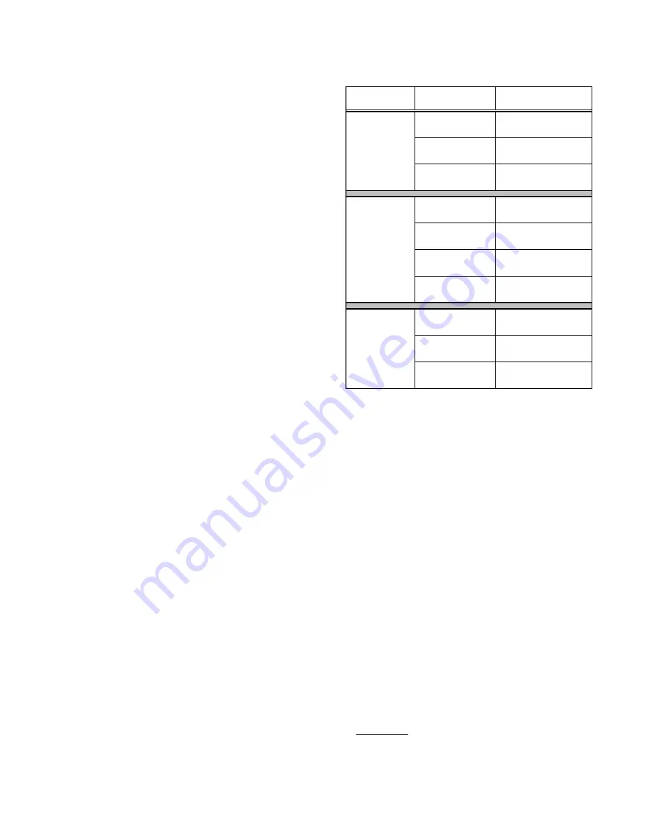
the demand to the ECM motor. The table below lists the
various ComfortNet systems, the operating mode, and
airflow demand source.
For example, assume the system is an air conditioner
matched with a furnace. With a call for low stage cooling,
the air conditioner will calculate the system’s low stage
cooling airflow demand. The air conditioner will then send a
fan request along with the low stage cooling airflow demand
to the furnace. Once received, the furnace will send the low
stage cooling airflow demand to the ECM motor. The ECM
motor then delivers the low stage cooling airflow. See the
applicable ComfortNet air conditioner or heat pump
installation manual for the airflow delivered during cooling
or heat pump heating.
System
System
Operating Mode
Airflow Demand
Source
Cooling
Air Conditioner
Heating
Furnace
Continuous Fan
Thermostat
Cooling
Heat Pump
Heat Pump Heating
Only
Heat Pump
Auxiliary Heating
Furnace
Continuous Fan
Thermostat
Cooling
Furnace
Heating
Furnace
Continuous Fan
Thermostat
F Non-
Comm 1stg Air
Conditioner
Air Condi
Furnace
Heat Pump +
Furnace
In continuous fan mode, the CTK0* thermostat provides the
airflow demand. The thermostat may be configured for a
low, medium, or high continuous fan speed. The low,
medium, and high fan speeds correspond to 25%, 50%, and
75%, respectively, of the furnaces’ maximum airflow
capability. During continuous fan operation, the thermostat
sends a fan request along with the continuous fan demand to
the furnace. The furnace, in turn, sends the demand to the
ECM motor. The ECM motor delivers the requested continuous
fan airflow.
F
OSSIL
F
UEL
A
PPLICATIONS
This furnace can be used in conjunction with a ComfortNet
compatible heat pump in a fossil fuel application. A fossil
fuel application refers to a combined gas furnace and heat
pump installation which uses an outdoor temperature sensor
to determine the most cost efficient means of heating (heat
pump or gas furnace). The balance point temperature may
be adjusted via the CTK0* thermostat advanced user menus
(see CTK0* instructions for additional information).
CTK0* W
IRING
NOTE:
A removable plug connector is provided with the
control to make thermostat wire connections. This plug may
be removed, wire connections made to the plug, and replaced.
It is
STRONGLY
recommended that you do not connect
multiple wires into a single terminal. Wire nuts are
recommended to ensure one 18 AWG wire is used for each
terminal. Failure to do so may result in intermittent
operation.