


32
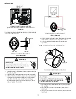
S-303 Induced Draft Blower Motor
WARNING
HIGH VOLTAGE
Disconnect ALL power before servicing or in
-
stalling this unit. Multiple power sources may
be present. Failure to do so may cause proper
-
ty damage, personal injury or death.
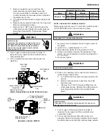
1. Remove burner compartment door to gain access to
the induced draft blower motor.
2. Disconnect the motor wire leads from its connection
point at the induced draft motor.
3. Using a ohmmeter, test for continuity between each of
the motor leads.
4. Touch one probe of the ohmmeter to the motor frame
(ground) and the other probe in turn to each lead
If the windings do not test continuous or a reading is
obtained to ground, replace the motor.
5. If the windings have a continuity reading, reconnect
wires. Turn power on to the furnace and turn the
thermostat on in the heating mode. Check voltage for
115V at the induced draft motor terminals during the
trial for ignition. If you have 115V and the motor does
not run, replace the induced draft motor.
6. After completing check and/or replacement of induced
draft motor, reinstall burner compartment door.
7. Turn on electrical power and verify proper unit
operation.
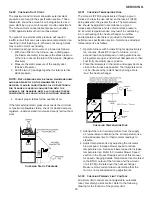
S-304 Checking Gas Valve (Redundant)
A combination redundant operator type gas valve which
provides all manual and automatic control functions
required for gas fired heating equipment is used.
The valve provides control of main burner gas flow,
pressure regulation, and 100 percent safety shut-off.
WARNING
Disconnect ALL power before servicing.
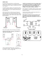
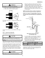
Single stage gas valves should be tested on the furnace
with 24 VAC connected to the gas valve and manometers
reading supply line and manifold pressures.
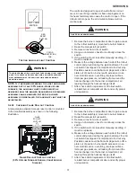
S-305 Checking Main Burners
Burners have been redesigned for 34.5” chassis furnaces.
Overall length and width dimensions remain the same as
40” model burners. The burners used 34.5” models have
burner head insert with larger diameter center hole and a
larger number of surrounding holes.
The main burners are used to provide complete
combustion of various fuels in a limited space, and transfer
this heat of the burning process to the heat exchanger.
Proper ignition, combustion, and extinction are primarily
due to burner design, orifice sizing, gas pressure, primary
and secondary air, vent and proper seating of burners.
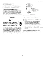
Beckett Burner
WARNING
Disconnect ALL power before servicing.
In checking main burners, look for signs of rust, oversized
and undersized carry over ports restricted with foreign
material, etc, burner cross-over slots should not be altered
in size.
S-306 Checking Orifices
S model furnaces have factory installed #43 natural gas
orifices.
The only time resizing is required is when a reduction in
firing rate is required for an increase in altitude or a furnace
is being converted for use with LP gas.
Orifices should be treated with care in order to prevent
damage. They should be removed and installed with a box-
end wrench in order to prevent distortion. In no instance
should an orifice be peened over and redrilled. This will
change the angle or deflection of the vacuum effect or
entraining of primary air, which will make it difficult to adjust
the flame properly. This same problem can occur if an
orifice spud of a different length is substituted.
SERVICING


