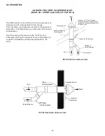
Daikin DM92SN Скачать руководство пользователя страница 29

29

S-200  Checking Duct Static

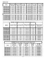
The maximum and minimum allowable external static 

pressures are found in the specification section. These 

tables also show the amount of air being delivered at a 

given static by a given motor speed or pulley adjustment.

The furnace motor cannot deliver proper air quantities 

(CFM) against statics other than those listed.

Too great of an external static pressure will result in 

insufficient air that can cause excessive temperature rise, 

resulting in limit tripping, etc. Whereas not enough static 

may result in motor overloading.

To determine proper air movement, proceed as follows:

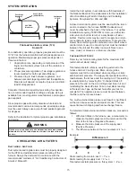
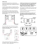
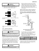
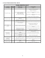
1.  With clean filters in the furnace, use a draft gauge 

(inclined manometer) to measure the static pressure 

of the return duct at the inlet of the furnace. (Negative 

Pressure)

2.  Measure the static pressure of the supply duct. 

(Positive Pressure)

3.  Add the two (2) readings together for total external 

static pressure.

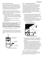
NOTE:  Both readings may be taken simultaneously 

and read directly on the manometer if so 

desired. If an air conditioner coil or Electronic 

Air Cleaner is used in conjunction with the 

furnace, the readings must also include theses 

components, as shown in the following drawing.

4.  Consult proper tables for the quantity of air.

If the total external static pressure exceeds the minimum 

or maximum allowable statics, check for closed dampers, 

registers, undersized and/or oversized poorly laid out duct 

work.

Checking Static Pressure 

S-201  Checking Temperature Rise 

The more air (CFM) being delivered through a given 

furnace, the less the rise will be; so the less air (CFM) 

being delivered, the greater the rise. The temperature 

rise should be adjusted in accordance to a given 

furnace specifications and its external static pressure. 

An incorrect temperature rise may result in condensing 

in or overheating of the heat exchanger. An airflow 

and temperature rise table is provided in the blower 

performance specification section. Determine and adjust 

temperature rise as follows:

1.  Operate furnace with burners firing for approximately 

ten minutes. Check BTU input to furnace - do not 

exceed input rating stamped on rating plate. Ensure 

all registers are open and all duct dampers are in their 

final (fully or partially open) position.

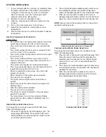
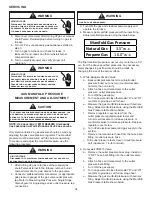
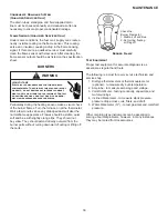
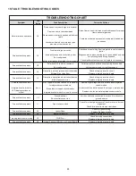
2.  Place thermometers in the return and supply ducts as 

close to the furnace as possible. Thermometers must 

not be influenced by radiant heat by being able to 

“see” the heat exchanger.

SUPPLY

    AIR

RETURN

    AIR 

Checking Temperature Rise 

3.  Subtract the return air temperature from the supply 

air temperature to determine the air temperature rise. 

Allow adequate time for thermometer readings to 

stabilize.

4.  Adjust temperature rise by adjusting the circulator 

blower speed. Increase blower speed to reduce 

temperature rise. Decrease blower speed to increase 

temperature rise. Refer to Circulator Blower Speed 

section in the Product Design section of this manual 

for speed changing details. Temperature rise is related 

to the BTUH output of the furnace and the amount 

of air (CFM) circulated over the heat exchanger. 

Measure motor current draw to determine that the 

motor is not overloaded during adjustments.

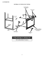
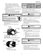
S-300  Checking Primary Limit Control

All primary limit controls are nonadjustable, automatic 

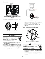
reset, bi-metal type limit control. Refer to the following 

drawing for the location of the primary limit.

SERVICING

Содержание DM92SN

Страница 1: ...this manual should service the equipment The manufacturer will not be responsible for any injury or property damage arising from improper service or service procedures If you service this unit you as...

Страница 2: ...RDS AND LABELS WARNING This unit should not be connected to or used in conjunction with any devices that are not design certified for use with this unit or have not been tested and approved by the man...

Страница 3: ...tly a fire or explosion may result causing property damage personal injury or loss of life do not store or use gasoline or other flammable vapors and liquids in the vicinity of this or any other appli...

Страница 4: ...ON MARCHE LEVER SHOWN INLET DU GAZ IN ON POS ARRIVEE DU GAZ INLET ARRIVEE GAS MANUAL GAS IN ON POS LEVER SHOWN MANUAL GAS INLET LEVER SHOWN ON MARCHE MANUAL GAS MANUEL EN POS DU GAZ ARRIVEE IN ON POS...

Страница 5: ...itial Release B 1st Revision Configuration M Upflow Horizontal Major Revision C Downflow Horizontal A Initial Release B 1st Revision Nox AFUE 80 80 AFUE 92 92 AFUE 96 96 AFUE 97 97 AFUE Cabinet Width...

Страница 6: ...arge process in Step 2 Use caution not to recharge your body with static electricity i e do not move or shuffle your feet do not touch ungrounded objects etc If you come in contact with an ungrounded...

Страница 7: ...unit overfiring POSITION SIDES REAR FRONT BOTTOM FLUE TOP Up ow 0 0 1 C 0 1 Horizontal 6 0 1 C 0 4 POSITION SIDES REAR FRONT BOTTOM FLUE TOP Down ow 0 0 1 NC 0 1 Horizontal 6 0 1 C 0 4 DM92SN DM96SN...

Страница 8: ...a Propane Gas Tanks and Piping WARNING Propane gas is heavier than air and any leaking gas can settle in any low areas or confined spaces To prevent property damage personal injury or death due to fir...

Страница 9: ...erflows electrical connection with the junction box located inside the burner compartment To make electrical connections through the opposite side of the furnace the junction box must be relocated to...

Страница 10: ...e junction box perform the following steps 1 Remove the burner compartment door 2 Remove and save the two screws securing the junction box to the side panel 3 Relocate junction box and associated plug...

Страница 11: ...lows simultaneous operation of two furnaces and forces the indoor blower motors of each furnace to operate synchronously into a common duct system Using the twinning function will require only field i...

Страница 12: ...ended that a LPLP03 kit also be installed The use of this kit will prevent the furnace from firing when the LP gas supply pressure is too low to support proper combustion All conversions must be perfo...

Страница 13: ...he cabinet A semi rigid connector to the gas piping may be used from there Use listed gas appliance connectors in accordance with their instructions Connectors must be fully in the same room as the fu...

Страница 14: ...ve before pressure testing supply piping system with test pressures equal to or less than 1 2 psig 3 48 kPA WARNING To avoid the possibility of explosion or fire never use a match or open flame to tes...

Страница 15: ...closed return duct system must be used with the return duct connected to the furnace NOTE Ductwork must never be attached to the back of the furnace For upflow installations requiring 1800 CFM or mor...

Страница 16: ...RS AFTER REMOVING SHEET METAL CUT USING TIN SNIPS PRESS OUT BY HAND SCRIBE LINES OUTLINING DUCT FLANGES Duct Flange Cut Outs Figure 12 When the furnace is used in connection with a cooling unit the fu...

Страница 17: ...d two side returns or 20 X 25 filter on bottom return or combination side bottom if furnace is connected to a cooling unit over 4 tons nominal capacity Change filters before occupants take ownership o...

Страница 18: ...imed prior to furnace startup To prime fill both sides of the drain trap with water This ensures proper furnace drainage upon startup and prohibits the possibility of flue gases escaping through the d...

Страница 19: ...The gas valve is de energized The inducer remains energized for the post purge period 15 seconds The indoor blower runs for the selected off delay period 90 seconds by default adjustable from 30 180 s...

Страница 20: ...period the cool circulator and air cleaner relay are de energized Cooling Mode Speed Selection To change the main blower speed in COOLING mode follow the following steps 1 Press the left or right swit...

Страница 21: ...DECK SCREWS SLOTS IN FILTER CLEAR SCREWS ON UNIT FRONT OF UNIT RETURN AIR CUTOUT AREA LOWER EDGE SCREW FILTER RACK ASSEMBLY FACE FILTER OPENING TOWARDS FRONT OF UNIT UNIT SIDE PANEL BASE OF UNIT EFR0...

Страница 22: ...in this manual under Vent Flue and Combustion Air Pipe Terminations for more information or consult the Installation and Operating Instructions IO 619 Vent Maintain 12 18 for Canada minimum clearance...

Страница 23: ...are NOT intended for use with single pipe indirect vent installations These vent kits must terminate outside the structure and may be installed with the intake and exhaust pipes located side by side o...

Страница 24: ...sformers VOLT OHM METER G ND PRIMARY SECONDARY TRANSFORMER R C METER READS 24 VOLTS LINE VOLTAGE NEUTRAL LINE VOLTAGE L1 HOT VOLT OHM METER METER READS 120 VOLTS VOLT OHM METER C R G ND N L1 VOLT OHM...

Страница 25: ...condensate Use longest radius fittings possible If using 3 venting make the transition from 2 to 3 as close as practically possible Make sure there is no flue gas recirculation into the combustion ai...

Страница 26: ...ty Ignition Control Test Control S 313 Gas Valve or Gas Supply Shut Off Turn Valves to On Position S 317 Faulty Induced Draft Blow er Test Induced Draft Motor S 303 Faulty Blow er Motor PSC Test Blow...

Страница 27: ...G on the integrated ignition control 5 With the blower motor in operation the voltage should be 115 volts 10 percent 6 If the reading falls below the minimum voltage check the line wire size Long runs...

Страница 28: ...A good capacitor will have a reading within 5 of the rated value S 16A Checking Air Circulator Blower Motor WARNING Disconnect ALL power before servicing 1 Remove blower compartment door to gain acces...

Страница 29: ...ss air CFM being delivered the greater the rise The temperature rise should be adjusted in accordance to a given furnace specifications and its external static pressure An incorrect temperature rise m...

Страница 30: ...ontinuous unless heat exchanger temperature is above limit control setting If not as above replace the control VOLT OHM METER COLOR IDENTIFYING TAB Testing Primary Limit Control 90 Furnaces 4 After co...

Страница 31: ...t close after manually resetting it must be replaced 6 Measure the voltage between each side of the rollout control and ground during the ignition attempt If a roll out switch has tripped it is import...

Страница 32: ...hould be tested on the furnace with 24 VAC connected to the gas valve and manometers reading supply line and manifold pressures S 305 Checking Main Burners Burners have been redesigned for 34 5 chassi...

Страница 33: ...al power and shut off gas supply 1 After turning off gas to furnace at the manual gas shutoff valve external to the furnace remove burner compartment door to gain access to the gas valve 2 Connect a c...

Страница 34: ...t pressure tap Refer to Measuring Gas Pressure Single Stage Valves figure for single stage valve outlet pressure tap connections WARNING Line Voltage now present 3 Turn ON the gas and electrical power...

Страница 35: ...el VR8215 Gas Rate Range Nominal High Stage 9 7 to 10 3 w c 10 0 w c Low Stage 5 7 to 6 3 w c 6 0 w c Propane Gas Manifold Gas Pressure S 308 Checking Hot Surface Ignitor Single stage furnaces use a 1...

Страница 36: ...mproper orifice size check orifice for obstruction S 310 Checking Pressure Switch The pressure control is a safety device to prevent the combustion cycle from occurring with inadequate venting caused...

Страница 37: ...ctor and neutral located on circuit board No voltage check for loose connection in the 2 pin connector or replace ignition control 4 If voltage is present in Steps 1 through 3 and the induced draft bl...

Страница 38: ...performance WARNING HIGH VOLTAGE Disconnect ALL power before servicing removing the filter or performing any other maintenance Multiple power sources may be present Failure to do so may cause propert...

Страница 39: ...sual check of the burner flames Turn the furnace on at the thermostat Wait a few minutes since any dislodged dust will alter the normal flame appearance Flames should be stable quiet soft and blue wit...

Страница 40: ...1 20 05 1 41 0130F00480 DM96SN1005CNAA 0 10 05 0 25 0 97 05 1 12 0130F00479 DM96SN1205DNAA 0 10 05 0 25 0 75 07 0 92 0130F00469 DC96SN0403BNAA 0 08 04 0 16 1 49 07 1 70 0130F00484 DC96SN0603BNAA 0 10...

Страница 41: ...nts can be made in 7 Secs increments from0 to 35 Secs Cool Off Delay Delay Seconds Default set at 65 Secs Adjustments can be made in 5 Secs increments from 0 to 120 Secs Blower Speed for Gas Heat Mode...

Страница 42: ...42 1 STAGE STATUS CODES STATUS MENU Idle Continous Fan Compressor Cooling Low Stage Compressor Cooling High Stage Gas heat Single Stage Control OEM test Mode Mode Main Menu...

Страница 43: ...anger Check circulator blower speed and performance Blocked filters restrictive ductwork improper circulator blower speed or failed circulator blower motor Correct speed or replace blower motor if nec...

Страница 44: ...ontrol module Blown fuse or tripped circuit breaker Correct condition which caused fuse to open replace fuse Integrated control module is non functional Replace non functional integrated control modul...

Страница 45: ...1269 1206 1133 1063 999 934 861 F06 1796 1744 1691 1638 1584 1532 1473 1422 F07 1874 1823 1775 1729 1675 1621 1567 1512 F08 1798 1754 1719 1672 1627 1585 1546 1497 F09 1991 1947 1900 1854 1808 1759 1...

Страница 46: ...1338 1269 1206 1133 1063 999 934 861 F06 1796 1744 1691 1638 1584 1532 1473 1422 F07 1874 1823 1775 1729 1675 1621 1567 1512 F08 1798 1754 1719 1672 1627 1585 1546 1497 F09 1991 1947 1900 1854 1808 1...

Страница 47: ...4 1309 1260 F05 1338 1269 1206 1133 1063 999 934 861 F06 1796 1744 1691 1638 1584 1532 1473 1422 F07 1874 1823 1775 1729 1675 1621 1567 1512 F08 1798 1754 1719 1672 1627 1585 1546 1497 F09 1991 1947 1...

Страница 48: ...45 1534 46 1478 48 1415 50 1357 1299 1246 F04 1600 44 1555 46 1505 47 1460 49 1412 50 1364 1309 1260 F01 1176 N A 1107 N A 1037 N A 969 N A 891 N A 825 753 692 F02 1773 42 1721 43 1671 44 1621 46 157...

Страница 49: ...039 1008 F05 874 828 791 750 703 655 602 547 F06 950 908 865 826 786 739 689 638 F07 1097 1056 1019 988 952 921 880 842 F08 1166 1127 1092 1060 1027 994 960 926 F09 1407 1373 1338 1308 1282 1253 1229...

Страница 50: ...3 1596 1538 1480 1422 1362 1306 1247 F05 1496 1437 1376 1315 1250 1189 1126 1056 F06 1640 1587 1527 1471 1414 1357 1294 1235 F07 1955 1937 1909 1860 1813 1765 1712 1662 F08 2086 2039 1991 1944 1896 18...

Страница 51: ...070 1039 1008 F05 874 828 791 750 703 655 602 547 F06 950 908 865 826 786 739 689 638 F07 1097 1056 1019 988 952 921 880 842 F08 1166 1127 1092 1060 1027 994 960 926 F09 1407 1373 1338 1308 1282 1253...

Страница 52: ...1653 1596 1538 1480 1422 1362 1306 1247 F05 1496 1437 1376 1315 1250 1189 1126 1056 F06 1640 1587 1527 1471 1414 1357 1294 1235 F07 1955 1937 1909 1860 1813 1765 1712 1662 F08 2086 2039 1991 1944 1896...

Страница 53: ...097 1070 1039 1008 F05 874 828 791 750 703 655 602 547 F06 950 908 865 826 786 739 689 638 F07 1097 1056 1019 988 952 921 880 842 F08 1166 1127 1092 1060 1027 994 960 926 F09 1407 1373 1338 1308 1282...

Страница 54: ...1520 1465 F04 1653 1596 1538 1480 1422 1362 1306 1247 F05 1496 1437 1376 1315 1250 1189 1126 1056 F06 1640 1587 1527 1471 1414 1357 1294 1235 F07 1955 1937 1909 1860 1813 1765 1712 1662 F08 2086 2039...

Страница 55: ...31 122 F02 1823 37 1776 38 1720 40 1679 41 1642 41 1597 1553 1504 F03 1778 38 1729 39 1690 40 1648 41 1605 42 1558 1497 1449 F04 1722 40 1660 41 1609 42 1553 44 1507 45 1455 1402 1350 F01 809 N A 740...

Страница 56: ...8 1078 F09 1427 1390 1362 1327 1297 1260 1224 1193 F01 715 658 589 524 465 412 360 279 F02 1415 1385 1355 1322 1291 1255 1219 1186 F03 1388 1360 1325 1291 1259 1223 1191 1157 F04 1290 1252 1215 1182 1...

Страница 57: ...1755 1710 1664 1619 1574 1526 1479 F05 1475 1421 1369 1314 1260 1207 1152 1097 F06 1626 1578 1522 1475 1427 1353 1328 1283 F07 1693 1639 1588 1542 1491 1437 1390 1340 F08 1775 1723 1674 1629 1580 152...

Страница 58: ...1118 1078 F09 1427 1390 1362 1327 1297 1260 1224 1193 F01 715 658 589 524 465 412 360 279 F02 1415 1385 1355 1322 1291 1255 1219 1186 F03 1388 1360 1325 1291 1259 1223 1191 1157 F04 1290 1252 1215 118...

Страница 59: ...804 1755 1710 1664 1619 1574 1526 1479 F05 1475 1421 1369 1314 1260 1207 1152 1097 F06 1626 1578 1522 1475 1427 1353 1328 1283 F07 1693 1639 1588 1542 1491 1437 1390 1340 F08 1775 1723 1674 1629 1580...

Страница 60: ...1154 1118 1078 F09 1427 1390 1362 1327 1297 1260 1224 1193 F01 715 658 589 524 465 412 360 279 F02 1415 1385 1355 1322 1291 1255 1219 1186 F03 1388 1360 1325 1291 1259 1223 1191 1157 F04 1290 1252 121...

Страница 61: ...656 1610 F04 1804 1755 1710 1664 1619 1574 1526 1479 F05 1475 1421 1369 1314 1260 1207 1152 1097 F06 1626 1578 1522 1475 1427 1353 1328 1283 F07 1693 1639 1588 1542 1491 1437 1390 1340 F08 1775 1723 1...

Страница 62: ...425 42 1370 1325 1271 F04 1537 39 1490 40 1447 41 1403 42 1354 44 1301 1247 1190 F01 1029 N A 959 N A 890 N A 811 N A 727 N A 647 579 511 F02 1814 33 1766 34 1722 34 1679 35 1637 36 1595 1555 1511 F03...

Страница 63: ...ANUFACTURER S SPECIFIED REPLACEMENT PARTS MUST BE USED WHEN SERVICING 3 IF ANY OF THE ORIGINAL WIRE AS SUPPLIED WITH THE FURNACE MUST BE REPLACED IT MUST BE REPLACED WITH WIRING MATERIAL HAVING A TEMP...

Отзывы: