


10
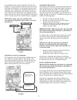
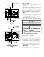
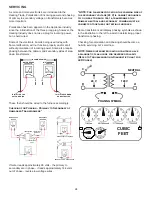
The integrated control module humidifier terminal 120V
HUM-H is energized with 115 volts whenever the induced
draft blower is energized. This terminal can also be used
to provide 115 volt power to a humidifier transformer. The
remaining primary transformer wire would be connected
to the Line N on the control board. The integrated control
module electronic air cleaner terminals EAC-H is energized
with 115 volts whenever the circulator blower is energized.
NOTE: Wire routing must not to interfere with
circulator blower operation, filter removal, or routine
maintenance.
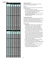
115 VAC EAC
115 VAC HUM
W R G C Y
Figure 1
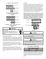
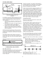
Connection of 24 Volt Humidifier
The integrated control module single humidifier terminal
“24 V HUM” is energized with 24 volts whenever the
induced draft blower is energized. Connect the common
side of the 24 volt humidifier to the “C” terminal of the
thermostat terminal strip on the control board.
24 VOLT HUM. &
HUMIDISTAT
W R G C Y
24V HUM Terminal is
energized when pressure
switch is closed
Figure 2
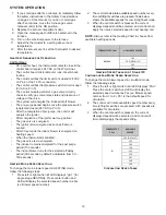
Junction Box Relocation
Line voltage connections can be made through either the
right or left side panel. The furnace is shipped configured
for a left side electrical connection. To make electrical
connections through the opposite side of the furnace,
the junction box must be relocated to the left side prior to
making electrical connections. To relocate the junction box,
perform the following steps.
1. Remove the burner compartment door.
2. Remove and save the two screws securing the
junction box to the side panel.
3. Relocate junction box and associated plugs and
grommets to opposite side panel. Secure with
screws removed in step.
IMPORTANT NOTE: Wire routing must not interfere
with circulator blower operation, filter removal
or routine maintenance.
To ensure proper unit grounding, the ground wire should
run from the furnace ground screw located inside the
furnace junction box all the way back to the electrical
panel.
NOTE: Do not use gas piping as an electrical
ground. To confirm proper unit grounding,
turn off the electrical power and perform the
following check.
1. Measure resistance between the neutral (white)
connection and one of the burners.
Resistance should measure 10 ohms or less.
This furnace is equipped with a blower door interlock
switch which interrupts unit voltage when the blower door
is opened for servicing. Do not defeat this switch.
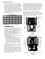
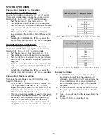
24 Volt Thermostat Wiring
Important Note: Wiring routing must not interfere
with circulator blower operation, filter removal
or routine maintenance.
Low voltage connections can be made through either the
right or left side panel. Thermostat wiring entrance holes
are located in the blower compartment. The following figure
shows connections for a “heat/cool system”.
This furnace is equipped with a 40 VA transformer to
facilitate use with most cooling equipment. Consult the
wiring diagram, located on the blower compartment door,
for further details of 115 Volt and 24 Volt wiring.


