SYSTEM OPERATION
39
•
Electronic air cleaner terminal and circulator blower
are de-energized.
•
Furnace awaits next call from thermostat.
F
AN
O
NLY
M
ODE
The normal operational sequence in fan only mode is as
follows:
•
R and G thermostat contacts close, initiating a call
for fan.
•
Integrated control module performs safety circuit
checks.
•
Circulator blower is energized on continuous fan speed
(25, 50, 75, 100% of the furnace’s maximum airflow
capability) following a five (5) second delay. Electronic
air cleaner terminal is energized.
•
Circulator blower runs, integrated control module moni-
tors safety circuits continuously.
•
R and G thermostat contacts open, completing the
call for fan.
•
Circulator blower is de-energized. Electronic air
cleaner terminal is de-energized.
•
Furnace awaits next call from thermostat.
D
EHUMIDIFICATION
M
ODE
The normal operational sequence in dehumidification
mode is as follows:
1.
R and Y1/G or Y1+Y2/G thermostat contacts close,
initiaing a call for cool.
2.
Integrated control module performs safety circuit
checks.
3.
Outdoor fan and compressor are energized to their ap-
propriate speed.
4.
Circulator blower is energized on the appropriate cool
speed at the level and time determined by the selected
ramping profile. Electronic air cleaner terminals are en-
ergized with circulator blower.
5.
Furnace circulator blower and outdoor cooling unit run
their appropriate speed, integrated control module moni-
tors safety circuits continuously.
6.
Dehumidistat opens on humidity rise allowing the fur-
nace circulator blower to operate at 85% of the cooling
speed during combined thermostat call for cooling and
dehumidistat call for dehumidification.
7.
Humidistat opens on humidity fall allowing furnace cir-
culator blower to switch back to normal cooling speed.
8.
R and Y1/G or Y1+Y2/G thermostat contacts open,
completing the call for cool.
9.
Outdoor fan and compressor are de-energized.
10. Circulator blower continues running during a cool off
delay period. The OFF delay time and airflow level are
determined by the selected ramping profile.
11. Electronic air cleaner terminals and circulator blower
are de-energized.
12. Furnace awaits next call from thermostat.
HEATING - Abnormal Operation
The following presents the probable causes of questionable
furnace operation and how to fix them. Look through the
observation window in the blower access door and make a
note of the error code displayed on the dual 7-segment dis-
play. Next, refer to the
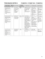
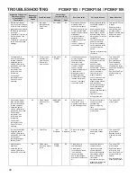
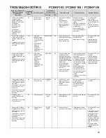
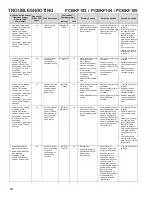
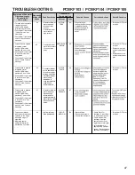
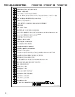
Troubleshooting Chart - ComfortNet™
on the following pages for an interpretation of the code dis-
played on the LED's for a description of the problem.
NOTE:
Use caution when reading the diagnostic codes from
the furnace control's dual, 7-segment LED's. The position
of the control within the furnace can lead to a misinterpreta-
tion of the error codes. With the control in an orienation as
shown below, codes on the dual, 7-segment LED's are read
left to right.
Memory Card Connector
Dual 7-Segment LED’s
2
Y2
HUM
O
G
Y1
C
W1
R
DE
W2
1
1.
Internal Control Failure with Integrated Ignition
Control.
Check for voltage to the furnace and low volt-
age at the control board. Check for blown fuse on the
control board. If the control determines it has an inter-
nal fault, it enters a locked-out state. Any of the situa-
tions mentioned will cause the dual, 7-segment LED's
to be
off
.
The control board should only be replaced
only after all other checks from the
Troubleshooting

