SERVICING
69
BLOWER HOUSING
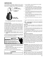
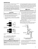
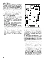
AUXILIARY LIMIT CONTROL
Auxiliary Limit Control Location
(80% Single-Stage Furnaces)
WARNING
HIGH
VOLTAGE
D
ISCONNECT
ALL
POWER BEFORE SERVICING OR
INSTALLING THIS UNIT.
M
ULTIPLE POWER SOURCES MAY
BE PRESENT.
F
AILURE TO DO SO MAY CAUSE PROPERTY
DAMAGE, PERSONAL INJURY OR DEATH.
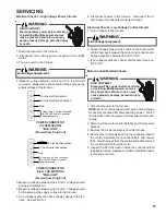
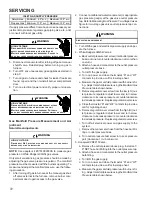
VOLT / OHM
METER
RED
RESET
BUTTON
COLOR
IDENTIFYING
TAB
Testing Auxiliary Limit Control
(80% & 90% Furnaces)
WARNING
T
O AVOID POSSIBLE FIRE, ONLY RESET THE AUXILIARY LIMIT CONTROL
ONCE.
I
F IT SHOULD OPEN A SECOND TIME, A QUALIFIED SERVICER
MUST DETERMINE WHY THE AUXILIARY LIMIT OPENED BEFORE
RESETTING AGAIN.
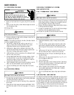
S-302 CHECKING FLAME ROLLOUT CONTROL
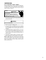
A temperature activated manual reset control is mounted
to the manifold assembly on 80% furnaces, as shown in
the following illustrations.
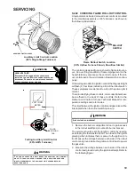
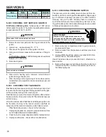
ROLLOUT
SWITCH
Flame Rollout Switch Location
(80% Upflow Furnace Shown, Downflow Similar)
The control is designed to open should a flame roll out oc-
cur. An over firing condition or flame impingement on the
heat shield may also cause the control to open. If the roll-
out control opens, the air circulation blower will run continu-
ously.
On two-stage models the ignition control the diagnostic light
will flash (4) four times indicating a trip of the rollout switch.
These symptoms are identical to a trip of the primary limit
control.
To aid in identifying these controls, color coded labels have
been affixed to the back of these controls. Refer to the
Rollout Limit Charts
in furnace Technical Manual for tem-
perature settings and color codes.
The circuit between the ignition control and gas valve will be
interrupted when the rollout switch opens up.
L
INE VOLTAGE NOW PRESENT
WARNING
1. Remove the burner compartment door to gain access
to the rollout switch(es) mounted to burner bracket.
The servicer should reset the ignition control by opening
and closing the thermostat circuit. Then look for the ignitor
glowing which indicates there is power to the ignition con-
trol. Measure the voltage between each side of the rollout
control and ground while the ignition control tries to power
the gas valve.
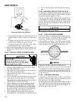
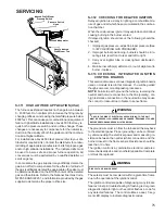
2. Measure the voltage between each side of the rollout
control and ground during the ignition attempt. Refer to
the following figure.

