PRODUCT DESIGN
32
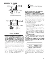
A heat pump thermostat with two stages of heat is required
to properly use the single-stage furnace with a heat pump.
A heat pump thermostat with three stages of heat is re-
quired to properly use the two-stage furnace with a heat
pump. Refer to dual fuel, AFE-18-60A installation manual
(IO-627) for additional wiring instructions.
CONTINUOUS FAN OPERATION
The two stage furnace control will energize ECM blower mo-
tor when the fan switch on the thermostat is turned to the
"ON" position. Continuous fan speed will be of the furnaces
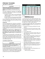
maximum airflow capability. 25%, 50%, 75%, or 100% se-
lectable by DIP switch setting or communicating thermo-
stat.
Example:
If the furnace’s maximum airflow capability
is 2000 CFM, the continuous fan speed will be 0.30 x
2000 CFM = 600 CFM.
For
the PCBKF103, PCBKF104, and PCBKF105
continu-
ous fan speeds that provide 25, 50, 75 and 100% of the
furnace’s maximum airflow capability are selectable via dip
switches S5- 3, 4.
Example:
If the furnace’s maximum airflow capability is
2000 CFM and 25% continuous fan speed
is selected, the continuous fan speed will be
0.25 x 2000 CFM = 500 CFM.
PCBKF105 IFC has the added feature of 24 VAC input to G
terminal when using a communicating thermostat (CTK0*).
ERV/HRV and other accessories can send a 24 VAC signal
to the G terminal and energize the continous fan.
3
4
25%
Off
Off
50%
On
Off
75%
Off
On
100%
On
On
Continuous Fan
SWITCH
S5
CIRCULATOR BLOWER SPEED ADJUSTMENT
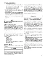
WARNING
HIGH
VOLTAGE
D
ISCONNECT
ALL
POWER BEFOR CHANGING SPEED TAPS.
M
ULTIPLE POWER SOURCES MAY BE PRESENT.
F
AILURE TO DO
SO MAY CAUSE PROPERTY DAMAGE, PERSONAL INJURY OR DEATH.
In general lower heating speeds will: reduce electrical con-
sumption, lower operating sound levels of the blower, and
increase the outlet air temperature delivered to the home.
The speeds available allow the blower performance to be
optimized for the particular homeowner’s needs.
TWO STAGE 2-STAGE VARIABLE SPEED
COMFORTNET™ FURNACES (WR50C51)
This furnace is equipped with a multi-speed circulator blower.
This blower provides ease in adjusting blower speeds. The
Specification Sheet applicable to your model provides an
airflow table, showing the relationship between airflow (CFM)
and external static pressure (E.S.P.), for the proper selec-
tion of heating and cooling speeds. The heating blower speed
is shipped set at “B”, and the cooling blower speed is set at
“D”. These blower speeds should be adjusted by the in-
staller to match the installation requirements so as to pro-
vide the correct heating temperature rise and correct cool-
ing CFM.
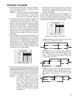
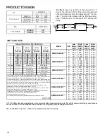
Use the dual 7-segment LED display adjacent to the
dipswitches to obtain the approximate airflow quantity. The
airflow quantity is displayed as a number on the display,
rounded to the nearest 100 CFM. The display alternates
airflow delivery indication and the operating mode indica-
tion.
Example:
The airflow being delivered is 1225 CFM. The
display indicates 12. If the airflow being delivered is 1275,
the display indicates 13.
1. Determine the tonnage of the cooling system installed
with the furnace. If the cooling capacity is in BTU/hr
divide it by 12,000 to convert capacity to TONs.
Example:
Cooling Capacity of 30,000 BTU/hr.
30,000/12,000 = 2.5 Tons
2. Determine the proper air flow for the cooling system.
Most cooling systems are designed to work with air
flows between 350 and 450 CFM per ton. Most manu-
facturers recommend an air flow of about 400 CFM per
ton.
Example:
2.5 tons X 400 CFM per ton = 1000 CFM
The cooling system manufacturer’s instructions must be
checked for required air flow. Any electronic air cleaners or
other devices may require specific air flows, consult instal-
lation instructions of those devices for requirements.
3. Knowing the furnace model, locate the high stage cool-
ing air flow charts in the Specification Sheet applicable
to your model. Look up the cooling air flow determined
in step 2 and find the required cooling speed and ad-
justment setting.
Example:
A DM80VC0603B* furnace installed with
a 2.5 ton air conditioning system. The air
flow needed is 1000 CFM. Looking at the
cooling speed chart for DM80VC0603B*,
find the air flow closest to 1000 CFM. A
cooling airflow of 990 CFM can be attained
by setting the cooling speed to “C” and the
adjustment to -10% trim.

