


68
SERVICING
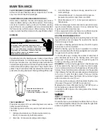
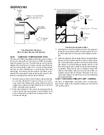
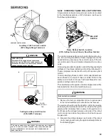
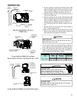
Location of Primary Limit
Primary Limit Control Location
(80% Upflow Furnace Shown, Counterflow Similar)
Style 1 drawing illustrates the Primary Limit used on the
80% furnaces.
Style 1
WARNING
HIGH
VOLTAGE
D
ISCONNECT
ALL
POWER BEFORE SERVICING OR
CHANGING ANY ELECTRICAL WIRING.
M
ULTIPLE POWER
SOURCES MAY BE PRESENT.
F
AILURE TO DO SO MAY CAUSE
PROPERTY DAMAGE, PERSONAL INJURY OR DEATH.
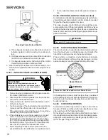
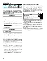
1.
Remove burner compartment door to gain access to
the primary limit.
2.
Remove low voltage wires at limit control terminals.
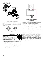
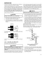
3.
With an ohmmeter, test between these two terminals
as shown in the following drawing. The ohmmeter
should read continuous unless heat exchanger tem-
perature is above limit control setting. If not as above,
replace the control.
VOLT / OHM
METER
Testing Primary Limit Control
(80% Furnaces)
4. After completing check and/or replacement of primary
limit control, reinstall burner compartment door.
5. Turn on electrical power and verify proper unit opera-
tion.
To aid in identifying these controls, refer to the
Primary
Limit Charts
in furnace Technical Manual for part number,
temperature setting and color(s) code.
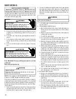
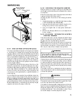
S-301 CHECKING AUXILIARY LIMIT CONTROL
Auxiliary Limit Control Location
The
80% two-stage
furnaces use an auxiliary limit (auto-
matic reset) control connected in series with the primary
limit control and rollout limit controls connected to the inte-
grated ignition control. If its temperature should be ex-
ceeded, it will open, interrupting the voltage to the gas valve
causing it to close. The auxiliary limit is located on the front
side of the blower housing, near the center, as shown in the
following illustration.


