


PRODUCT DESIGN
27
– Semi-rigid metallic tubing and metallic fittings. Alu-
minum alloy tubing must not be used in exterior loca-
tions. In order to seal the grommet cabinet penetra-
tion, rigid pipe must be used to reach the
outside
of the cabinet. A semi-rigid connector to
the gas piping may be used from there.
10. Use listed gas appliance connectors in accordance with
their instructions. Connectors must be fully in the same
room as the furnace.
11. Protect connectors and semi-rigid tubing against physi-
cal and thermal damage when installed. Ensure alumi-
num-alloy tubing and connectors are coated to protect
against external corrosion when in contact with masonry,
plaster, or insulation, or subjected to repeated wetting
by liquids such as water (except rain water), detergents,
or sewage.
CAUTION
E
DGES OF SHEET METAL HOLES MAY BE SHARP.
U
SE GLOVES A PRECAUTION
WHEN REMOVING HOLE PLUGS.
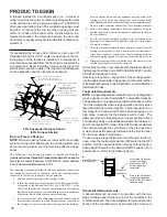
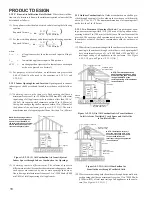
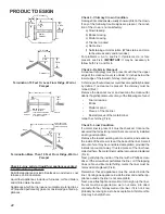
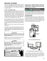
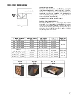
DIRECT/STANDARD INLET PIPING
When gas piping enters
directly
to the gas valve through the
standard
inlet hole (upflow through the right side panel), the
installer must supply straight pipe with a ground joint union
to reach the exterior of the furnace.
NOTE:
The rigid pipe
must be long enough to reach the outside of the cabinet. A
semi-rigid connector to the gas piping can be used outside
the cabinet per local codes.
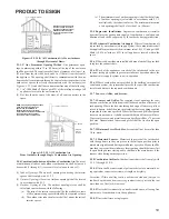
INDIRECT/ALTERNATE INLET PIPING
When gas piping enters
indirectly
to the gas valve through
the
alternate
gas inlet hole the installer must supply the
following fittings (starting from the gas valve) to reach the
outside of the cabinet :
•
Coupling.
•
90 degree elbow.
•
2 inch close nipple.
•
90 degree elbow.
•
Straight pipe, with a ground joint union, to reach the
exterior of the furnace.
GAS PIPING CHECKS
Before placing unit in operation, leak test the unit and gas
connections.
WARNING
T
O AVOID THE POSSIBLITY OF EXPLOSION OR FIRE, NEVER USE A MATCH
OR OPEN FLAME TO TEST FOR LEAKS.
Check for leaks using an approved chloride-free soap and
water solution, an electronic combustible gas detector, or
other approved testing methods.
NOTE:
Never exceed specified pressures for testing. Higher
pressure may damage the gas valve and cause subsequent
overfiring, resulting in heat exchanger failure. Disconnect this
unit and shutoff valve from the gas supply piping system
before pressure testing the supply piping system with pres-
sures in excess of 1/2 psig (3.48 kPa). Isolate this unit from
the gas supply piping system by closing its external manual
gas shutoff valve before pressure testing supply piping sys-
tem with test pressures equal to or less than 1/2 psig (3.48
kPa).
PROPANE GAS TANKS AND PIPING
WARNING
P
ROPANE GAS IS HEAVIER THAN AIR AND ANY LEAKING GAS CAN SETTLE IN
ANY LOW AREAS OR CONFINED SPACES.
T
O PREVENT PROPERTY DAMAGE,
PERSONAL INJURY, OR DEATH DUE TO FIRE OR EXPLOSION CAUSED BY A
PROPANE GAS LEAK, INSTALL A GAS DETECTION WARNING DEVICE.
A gas detecting warning system is the only reliable way to
detect a propane gas leak. Iron oxide (rust) can reduce the
level of odorant in propane gas. Do not rely on your sense of
smell. Contact a local propane gas supplier about installing
a gas detecting warning system. If the presence of gas is
suspected, follow the instructions on Pages 10-12 of this
manual.
All propane gas equipment must conform to the safety stan-
dards of the National Board of Fire Underwriters, NBFU
Manual 58.
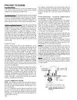
For satisfactory operation, propane gas pressure must be
11 inch WC at the furnace manifold with all gas appliances
in operation. Maintaining proper gas pressure depends on
three main factors:
1. Vaporization rate, depending on temperature of the liq-
uid, and “wetted surface” area of the container or con-
tainers.
2. Proper pressure regulation. (Two-stage regulation is rec-
ommended for both cost and efficiency).
3. Pressure drop in lines between regulators, and between
second stage regulator and the appliance. Pipe size will
depend on length of pipe run and total load of all appli-
ances.
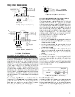
Complete information regarding tank sizing for vaporization,
recommended regulator settings, and pipe sizing is avail-
able from most regulator manufacturers and propane gas
suppliers. Use a pipe thread sealant approved for natural
gas and LP gas.
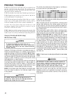
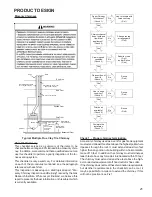
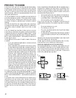
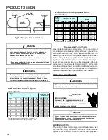
Refer to the following illustration for typical propane gas in-
stallations and piping.


