PRODUCT DESIGN
17
reduce the speed of the circulator blower during operation in
the cooling mode. To be compatible with these furnaces, a
dehumidistat must operate on 24 VAC and utilize a switch
which
opens on humidity rise
.
Refer to
Electrical Connec-
tions - 24 Volt Dehumidistat Wiring
section in this manual
or the installation instructions for correct installation proce-
dure.
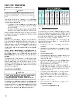
Thermostat and Dehumidistat Location
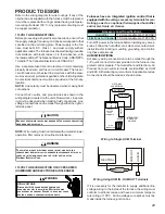
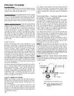
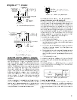
In an area having good air circulation, locate the thermostat
and dehumidistat (if applicable) about five feet high on a vi-
bration-free inside wall. Do not install the thermostat or de-
humidistat where it may be influenced by any of the follow-
ing:
•
Drafts, or dead spots behind doors, in corners, or un-
der cabinets.
•
Hot or cold air from registers.
•
Radiant heat from the sun.
•
Light fixtures or other appliances.
•
Radiant heat from a fireplace.
•
Concealed hot or cold water pipes, or chimneys.
•
Unconditioned areas behind the thermostat and de-
humidistat, such as an outside wall.
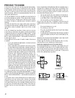
HOT
COLD
DRAFTS OR DEAD SPOTS
-BEHIND DOORS
-IN CORNERS
-UNDER CABINETS
Thermostat Influences
Consult the instructions packaged with the thermostat and
dehumidistat for mounting instructions and further precau-
tions.
COMBUSTION AND VENTILATION AIR
REQUIREMENTS
WARNING
P
OSSIBLE PROPERTY DAMAGE, PERSONAL INJURY OR DEATH MAY OCCUR
IF THE FURNACE IS NOT PROVIDED WITH ENOUGH FRESH AIR FOR PROPER
COMBUSTION AND VENTILATION OF FLUE GASES. MOST HOMES REQUIRE
OUTSIDE AIR BE SUPPLIED TO THE FURNACE AREA.
Improved construction and additional insulation in buildings
have reduced heat loss by reducing air infiltration and es-
cape around doors and windows. These changes have helped
in reducing heating/cooling costs but have created a prob-
lem supplying combustion and ventilation air for gas fired
and other fuel burning appliances. Appliances that pull air
out of the house (clothes dryers, exhaust fans, fireplaces,
etc.) increase the problem by starving appliances for air.
If this furnace is to be installed in the same space with other
gas appliances, such as a water heater, ensure there is an
adequate supply of combustion and ventilation air for the
other appliances. Refer to the latest edition of the National
Fuel Gas Code NFPA 54/ANSI Z223.1 (Section 9.3), or CAN/
CGA B149 Installation Codes (Sections 7.2, 7.3, or 7.4), or
applicable provisions of the local building codes for deter-
mining the combustion air requirements for the appliances.
Most homes will require outside air be supplied to the fur-
nace area by means of ventilation grilles or ducts connect-
ing directly to the outdoors or spaces open to the outdoors
such as attics or crawl spaces.
The following information on air for combustion and ventilation
is reproduced from the
National Fuel Gas Code NFPA 54/ANSI
Z223.1 Section 9.3.
9.3* Air for Combustion and Ventilation.
9.3.1 General.
9.3.1.1
Air for combustion, ventilation, and dilution of flue gases for
appliances installed in buildings shall be obtained by application of one
of the methods covered in 9.3.2 through 9.3.6. Where the requirements
of 9.3.2 are not met, outdoor air shall be introduced in accordance with
methods covered in 9.3.3 through 9.3.6.
Exception No. 1: This provision shall not apply to direct vent appliances.
9.3.1.2
Appliances of other than natural draft design and other than
Category 1 vented appliances shall be provided with combustion, ven-
tilation, and dilution air in accordance with the appliance manufacturer’s
instructions.
9.3.1.3
Appliances shall be located so as not to interfere with proper
circulation of combustion, ventilation, and dilution air.
9.3.1.4
Where used, a draft hood or a barometric draft regulator shall be
installed in the same room or enclosure as the appliance served so as to
prevent any difference in pressure between the hood or regulator and the
combustion air supply.
9.3.1.5
Makeup air requirements for the operation of exhaust fans, kitchen
ventilation systems, clothes dryers, and fireplaces shall be considered in
determining the adequacy of a space to provide combustion air require-
ments.
9.3.2 Indoor Combustion Air.
The required volume of indoor air shall
be determined in accordance with the method in 9.3.2.1 or 9.3.2.2 ex-
cept that where the air infiltration rate is known to be less than 0.40
ACH,
the method in 9.3.2.2 shall be used. The total required volume
shall be the sum of the required volume calculated for all appliances
located within the space. Rooms communicating directly with the space
in which the appliances are installed through openings not furnished
with doors, and through combustion air openings sized and located in
accordance with 9.3.2.3, are considered a part of the required volume.
9.3.2.1* Standard Method.
The minimum required volume shall be 50
ft
3
per 1,000/Btu/hour (4.8m
3
/kW).

