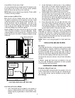
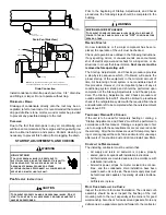
background image

4


industrial processes may also be sources of chlorine/fluo

-

rine compounds.  

•  To avoid possible illness or death of the building occupants, 

do NOT locate outside air intake device (economizer, man-

ual fresh air intake, motorized fresh air intake) too close to 

an exhaust outlet, gas vent termination, or plumbing vent 

outlet. For specific distances required, consult local codes.

•  Allow minimum clearances from the enclosure for fire pro

-

tection, proper operation, and service access (see Unit 

Clearances). These clearances must be permanently 

maintained.

•  When the unit is heating, the temperature of the return air 

entering the unit must be a minimum of 55°F.

g

rOund

 l

evel

 i

nstallatiOns

 O

nly

:

•  When the unit is installed on the ground adjacent to the 

building, a level concrete (or equal) base is recommended. 

Prepare a base that is 3” larger than the package unit foot-

print and a minimum of 3” thick.

•  The base should also be located where no runoff of water 

from higher ground can collect in the unit.

r

OOf


tOP

 i

nstallatiOns

 O

nly

:

•  To avoid possible property damage or personal injury, the 

roof  must  have  sufficient  structural  strength  to  carry  the 

weight of the unit(s) and snow or water loads as required 

by local codes.  Consult a structural engineer to determine 

the weight capabilities of the roof.

•  The  unit  may  be  installed  directly  on  wood  floors  or  on 

Class A, Class B, or Class C roof covering material.

•  To  avoid  possible  personal  injury,  a  safe,  flat  surface  for 

service personnel should be provided.

•  Adequate clearances from the unit to any adjacent public 

walkways, adjacent buildings, building openings or open-

able windows must be maintained in accordance with Na-

tional Codes.

u

nit

 P

reCautiOns

•  Do not stand or walk on the unit.
•  Do not drill holes anywhere in panels or in the base frame 

of the unit (except where indicated).  Unit access panels 

provide structural support.

•  Do not remove any access panels until unit has been in-

stalled on roof curb or field supplied structure.

•  Do not roll unit across finished roof without prior approval of 

owner or architect.

•  Do not skid or slide on any surface as this may damage 

unit base.  The unit must be stored on a flat, level surface.  

Protect the condenser coil because it is easily damaged.

r

OOf

 C

urb

 i

nstallatiOns

 O

nly

:

Curb installations must comply with local codes and should 

be done in accordance with the established guidelines of 

the National Roofing Contractors Association.
Proper unit installation requires that the roof curb be firmly 

and permanently attached to the roof structure.  Check for 

adequate fastening method prior to setting the unit on the 

curb.

Full perimeter roof curbs are available from the factory and 

are shipped unassembled. Field assembly, squaring, level-

ing and mounting on the roof structure are the responsibility 

of the installing contractor.   All required hardware neces-

sary for the assembly of the sheet metal curb is included in 

the curb accessory. 

•  Sufficient structural support must be determined prior to lo

-

cating and mounting the curb and package unit.

•  Ductwork must be constructed using industry guidelines.  

The duct work must be placed into the roof curb before 

mounting the package unit. Our full perimeter curbs include 

duct connection frames to be assembled with the curb.  

Cantilevered type curbs are not available from the factory.

•  Curb  insulation,  cant  strips,  flashing  and  general  roofing 

material are furnished by the contractor.

The curbs must be supported on parallel sides by roof mem-

bers.  The roof members must not penetrate supply and re-

turn duct opening areas as damage to the unit might occur.

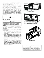
NOTE: 

The unit and curb accessories are designed to allow 

vertical duct installation before unit placement.  Duct instal-

lation after unit placement is not recommended.

See the manual shipped with the roof curb for assembly and 

installation instructions.

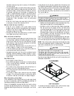
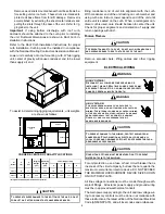
CLEARANCES

UNIT CLEARANCES

*In situations that have multiple units, a 48” minimum clear-

ance is required between the condenser coils.

T

O


PREVENT


POSSIBLE


EQUIPMENT


DAMAGE

PROPERTY


DAMAGE

PERSONAL


INJURY


OR


DEATH

THE


FOLLOWING


BULLET


POINTS


MUST


BE


OBSERVED


WHEN


INSTALLING


THE


UNIT

.

WARNING

A

LL


CURBS


LOOK


SIMILAR

. T

O


AVOID


INCORRECT


CURB


POSITIONING

CHECK


JOB


PLANS


CAREFULLY


AND


VERIFY


MARKINGS


ON


CURB


ASSEMBLY

. I

NSTRUCTIONS


MAY


VARY


IN


CURB


STYLES


AND


SUPERSEDES


INFORMATION


SHOWN

.

CAUTION

48"

48"

48"

48"

Содержание DCC Series

Страница 1: ... 3 Clearances 4 Roof Curb Post Installation Checks 5 Roof Top Duct Connections 5 Rigging Details 5 Electrical Wiring 6 Circulating Air and Filters 8 Condensate Drain Connection 8 Startup Adjustments and Checks 9 Air Flow Adjustments 10 INSTALLATION INSTRUCTIONS WARNING PROP 65 WARNING FOR CALIFORNIA CONSUMERS Cancer and Reproductive Harm www P65Warnings ca gov 0140M00517 A ONLY PERSONNEL THAT HAVE...

Страница 2: ...d performance is achieved after 72 hours of operation Rated performance is delivered at the specified airflow See product specification sheet for light commercial models Specification sheets can be found at www daikinac com for Daikin brand products Within the website please select the commercial products menu and then select the submenu for the type of product to be installed such as air conditio...

Страница 3: ...pt of any visible damage to shipment or container 2 Notify carrier promptly and request an inspection 3 In case of concealed damage carrier should be notified as soon as possible preferably within 5 days 4 File the claim with the following supporting documents a Original Bill of Lading certified copy or indemnity bond b Original paid freight bill or indemnity in lieu thereof c Original invoice or ...

Страница 4: ...de on any surface as this may damage unit base The unit must be stored on a flat level surface Protect the condenser coil because it is easily damaged Roof Curb Installations Only Curb installations must comply with local codes and should be done in accordance with the established guidelines of the National Roofing Contractors Association Proper unit installation requires that the roof curb be fir...

Страница 5: ...ET UNIT ON CURB CAUTION Horizontal Discharge To convert to horizontal discharge remove the covers over the horizontal duct connections save washered screws Refer to IOD 7006 included in the literature pack for install ing horizontal duct covers to the downflow duct connections Flexible duct connectors between the unit and ducts are rec ommended Insulate and weatherproof all external ductwork and j...

Страница 6: ...an tilever curb is used care should be taken to center the unit Check for proper alignment and orientation of supply and return openings with duct Rigging Removal Remove spreader bars lifting cables and other rigging equipment ELECTRICAL WIRING For unit protection use a fuse or hacr circuit breaker that is in excess of the circuit ampacity but less than or equal to the maximum overcurrent protecti...

Страница 7: ...e absence of local codes with the latest edition of the National Electrical Code ANSI NFPA 70 A ground lug is provided for this purpose Size grounding conductor in accordance with Table 250 95 of the National Electrical Code Do not use the ground lug for connecting a neutral conductor Remove plug in panel located at the condenser end of unit and route conduit to control box Remove plug in control ...

Страница 8: ...the thermostat 3 Use 18 AWG wire for 24V control wiring runs not ex ceeding 75 feet Use 16 AWG wire for 24V control wir ing runs not exceeding 125 feet Use 14 AWG wire for 24V control wiring runs not exceeding 200 feet Low volt age wiring may be National Electrical Code NEC Class 2 where permitted by local codes 4 Route thermostat wires from sub base terminals to the unit Control wiring should ent...

Страница 9: ...a step by step sequence which if followed will assure the proper startup of the equipment in the minimum amount of time Air balancing of duct system is not considered part of this procedure However it is an important phase of any air conditioning system startup and should be performed upon completion of the Startup Adjustments and Checks proce dure The Startup Adjustments and Checks procedure at o...

Страница 10: ... 4 3 Percent Voltage Unbalance 100 x 1 8 Percent voltage unbalance MUST NOT exceed 2 4 216 400 216 100 X AIR FLOW ADJUSTMENTS NOTE For 2 speed models airflow adjustments must be made on high speed i e 2nd stage cooling or in heat mode Refer to Motor Sheave Adjustments section When the final adjustments are complete the current draw of the motor should be checked and compared to the full load curre...

Страница 11: ...RCE lbs SHEAVE DIAMETER in TYPE New V belts will drop rapidly during the first few hours of use Check tension frequently during the first 24 hours of operation Tension should fall between the minimum and maximum force To determine the deflection distance from a normal position measure the distance from sheave to sheave using a straightedge or a cord This is your refer ence line On multiple belt dr...

Страница 12: ...G After the cooling mode is checked out turn the thermo stat system switch to OFF 10 Turn the thermostat system switch to HEAT and fan switch to AUTO 11 Slowly raise the heating temperature setting When the heating first stage makes contact stop raising the tem perature setting The compressor blower and fan should now be running with the reversing valve in the de ener gized heating position After ...

Страница 13: ...ature of the refrigerant in the outdoor coil must be below the tempera ture of the outdoor air in order to extract heat from the air Thus the greater the difference in the outdoor temperature and the outdoor coil temperature the greater the heating capacity of the heat pump This phenomenon is a char acteristic of a heat pump It is a good practice to provide supplementary heat for all heat pump ins...

Страница 14: ...ENCY OR EQUIPMENT DAMAGE DUE TO DUST AND LINT BUILD UP ON INTERNAL PARTS NEVER OPERATE UNIT WITHOUT AN AIR FILTER INSTALLED IN THE RETURN AIR SYSTEM Cabinet Finish Maintenance Use a fine grade automotive wax on the cabinet finish to maintain the finish s original high luster This is especial ly important in installations with extended periods of direct sunlight Clean Outside Coil Qualified Service...

Страница 15: ... shift a Undercharged check for leaks b Valve Body Damaged Replace valve c Unit Properly Charged If it is on the heating cycle raise the discharge pressure by restricting airflow through the indoor coil If the valve does not shift tap it lightly on both ends with a screwdriver handle DO NOT TAP THE VALVE BODY If the unit is on the cooling cycle raise the discharge pressure by restricting airflow t...

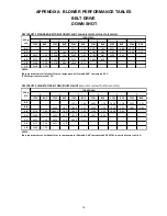
Страница 16: ...representsdry coil without filter to compensate for filter add 0 08 to measured E S P SCFM correction for wet coil 4 CFM BHP CFM BHP CFM BHP CFM BHP CFM BHP CFM BHP 0 6 2793 1 64 2603 1 39 2450 1 18 2270 0 97 0 8 2903 1 87 2696 1 57 2369 1 23 2236 1 05 1987 0 82 1 0 2776 1 86 2682 5 1 69 2445 1 38 2196 1 12 1968 0 90 1 2 2599 1 71 2539 1 57 2310 1 29 1932 0 96 1 4 2424 1 57 2305 1 40 2032 1 11 1 6...

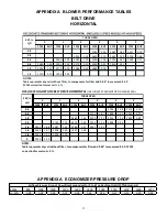
Страница 17: ...ORIZONTAL INCLUDES 2 SPEED MOTOR ON HIGH SPEED CFM BHP CFM BHP CFM BHP CFM BHP CFM BHP CFM BHP 0 6 2746 1 38 2515 1 12 0 8 2721 1 47 2494 1 21 2261 0 97 1 0 2689 1 56 2500 1 32 2255 1 06 1994 0 83 1 2 2752 1 74 2473 1 40 2252 1 15 1996 0 91 1 4 2802 1 88 2487 1 53 2286 1 27 2037 1 02 1 6 2553 1 67 2308 1 40 1997 1 08 1 8 2355 1 51 2014 1 19 2 2055 1 29 NOTES Table representsdry coil without filter...

Страница 18: ... 30 4 35 EHK4 20 24 0 3 3 37 9 40 EHK4 25 30 1 3 3 45 5 50 14 3 20 EHK4 10 12 0 18 6 20 EHK4 15 18 0 26 1 30 EHK4 20 24 0 33 6 35 EHK4 25 30 1 41 3 45 3 3 17 6 25 EHK4 10 12 0 3 3 22 8 25 EHK4 15 18 0 3 3 30 3 35 EHK4 20 24 0 3 3 37 8 40 EHK4 25 30 1 3 3 45 4 50 12 3 15 EHK7 10 10 0 15 4 20 EHK7 15 15 1 21 8 25 EHK7 20 20 0 27 9 30 EHK7 25 25 1 34 3 35 2 6 14 9 20 EHK7 10 10 0 2 6 18 6 20 EHK7 15 ...

Страница 19: ... 41 8 45 EHK4 20 24 0 3 3 49 3 50 EHK4 25 30 1 3 3 57 0 60 14 3 20 EHK4 10 12 0 29 3 30 EHK4 15 18 0 36 8 40 EHK4 20 24 0 44 3 45 EHK4 25 30 1 52 0 60 3 3 17 6 25 EHK4 10 12 0 3 3 32 6 35 EHK4 15 18 0 3 3 40 1 45 EHK4 20 24 0 3 3 47 6 50 EHK4 25 30 1 3 3 55 3 60 12 3 15 EHK7 10 10 0 24 8 25 EHK7 15 15 1 31 1 35 EHK7 20 20 0 37 3 40 EHK7 25 25 1 43 6 45 2 6 14 9 20 EHK3 10 10 0 2 6 27 4 30 EHK3 15 ...

Страница 20: ...DEL NUMBER MINIMUM CFM EHK 10 2100 EHK 15 2100 EHK 20 2100 EHK 25 2100 MINIMUM AIR FLOW FOR ELECTRIC HEAT 6 TON ATTENTION INSTALLING PERSONNEL Use only the heater kit specified for each model as dictated by the table above ...

Страница 21: ...URN SUPPLY 12 17 7 3 8 11 25 6 1 4 4 7 8 DRAIN THRU CURB LOCATION EMBOSS FOR THRU THE BASE UTILITIES BOTTOM VIEW OF UNIT 8 3 16 5 7 8 19 7 16 27 3 8 47 1 2 4 1 2 7 1 2 SUPPLY RETURN NOTE Refer to IOD 7006 included in the literature pack for installing horizontal duct covers ...

Страница 22: ...n the unit for the most up to date wiring HIGH VOLTAGE DISCONNECT ALL POWER BEFORE SERVICING OR INSTALLING THIS UNIT MULTIPLE POWER SOURCES MAY BE PRESENT FAILURE TO DO SO MAY CAUSE PROPERTY DAMAGE PERSONAL INJURY OR DEATH APPENDIX D WIRING DIAGRAMS DCC072 208 230 460 575 3 60 1 SPEED ...

Страница 23: ...the unit for the most up to date wiring HIGH VOLTAGE DISCONNECT ALL POWER BEFORE SERVICING OR INSTALLING THIS UNIT MULTIPLE POWER SOURCES MAY BE PRESENT FAILURE TO DO SO MAY CAUSE PROPERTY DAMAGE PERSONAL INJURY OR DEATH 23 WIRING DIAGRAMS DCH072 208 230 3 60 1 SPEED ...

Страница 24: ...ring diagram on the unit for the most up to date wiring HIGH VOLTAGE DISCONNECT ALL POWER BEFORE SERVICING OR INSTALLING THIS UNIT MULTIPLE POWER SOURCES MAY BE PRESENT FAILURE TO DO SO MAY CAUSE PROPERTY DAMAGE PERSONAL INJURY OR DEATH 24 DCH072 460 575 3 60 1 SPEED ...

Страница 25: ...NAL USE COPPER CONDUCTORS ONLY 2 IF OPTIONAL ECONOMIZER IS INSTALLED REMOVE ECON SHRT PLM AND CONNECT ECON PLM TO ECON PLF 3 TB3 LOW VOLTAGE TERMINAL BLOCK 4 TERMINALS FOR 24VAC PWR RD BR WIRE AND 6 TERMINALS FOR 24VAC COM BL WIRE 4 CONNECTIONS SHOWN ARE FOR 1 STAGE HEAT OPERATION WHEN 2 STAGE OPERATION IS REQIRED REMOVE JUMPER WIRE CONNECTING W2 TO W1 ON TB1 5 IF OPTIONAL SMOKE DETECTOR S ARE INS...

Страница 26: ...T1 T2 T3 CC OR RD BK OR RD YL BK T1 T3 COMP T2 EM BR OR RD BK WH OR BL GY BL YL GY BL YL GR RD BK 2 3 4 24V CNTL VOLTAGE LINE VOLTAGE TR1 LOW VOLTAGE FIELD WIRING HIGH VOLTAGE Y2 2ND STAGE COOL CALL OUTPUT Y1 1ST STAGE COOL CALL OUTPUT W2 2ND STAGE HEAT CALL OUTPUT W1 1ST STAGE HEAT CALL OUTPUT G C R TB1 CONNECTION 24VAC PWR INPUT THERMOSTAT IN OUT 24VAC COM INPUT FAN CALL OUTPUT THERMOSTAT CO NNE...

Страница 27: ...P T2 EM OR RD BK WH OR BL GY BL YL GY BL YL GR RD BK 2 3 4 24V CNTL VOLTAGE LINE VOLTAGE TR1 LOW VOLTAGE FIELD WIRING HIGH VOLTAGE Y2 2ND STAGE COOL CALL OUTPUT Y1 1ST STAGE COOL CALL OUTPUT W2 2ND STAGE HEAT CALL OUTPUT W1 1ST STAGE HEAT CALL OUTPUT G C R TB1 CONNECTION 24VAC PWR INPUT THERMOSTAT IN OUT 24VAC COM INPUT FAN CALL OUTPUT THERMOSTAT CONNECTIONS YELLOW PINK STRIPE YELLOW YL PK BL PK B...

Страница 28: ... TO ECON PLF 3 TB3 LOW VOLTAGE TERMINAL BLOCK 4 TERMINALS FOR 24VAC PWR RD BR WIRE AND 6 TERMINALS FOR 24VAC COM BL WIRE 4 CONNECTIONS SHOWN ARE FOR 1 STAGE HEAT OPERATION WHEN 2 STAGE OPERATION IS REQIRED REMOVE JUMPER WIRE CONNECTING W2 TO W1 ON TB1 5 IF OPTIONAL SMOKE DETECTOR S ARE INSTALLED REMOVE JUMPER WIRE CONNECTING S1 TO S2 ON TB1 WIRE CONNECTIONS FROM ACCESSORY KIT CONNECT RD WIRE TO TB...

Страница 29: ...2 L3 T1 T2 T3 CC OR RD BK OR RD YL BK T1 T3 COMP T2 EM OR RD BK WH OR BL GY BL YL GY BL YL GR RD BK 2 3 4 24V CNTL VOLTAGE LINE VOLTAGE TR1 LOW VOLTAGE FIELD WIRING HIGH VOLTAGE Y2 2ND STAGE COOL CALL OUTPUT Y1 1ST STAGE COOL CALL OUTPUT W2 2ND STAGE HEAT CALL OUTPUT W1 1ST STAGE HEAT CALL OUTPUT G C R TB1 CONNECTION 24VAC PWR INPUT THERMOSTAT IN OUT 24VAC COM INPUT FAN CALL OUTPUT THERMOSTAT CONN...

Страница 30: ...30 WIRING DIAGRAMS FOR MODELS WITH DDC CONTROLS FOR COMPLETE INFORMATION AND INSTALLATION INSTRUCTIONS FOR MODELS WITH DDC CONTROLS SEE MANUAL DK DDC TGD XXX ...

Страница 31: ...3 60 SEE NOTE 2 BI7 CFS PK BL PK RD YL GR 1 4 HEATER PLF BK BK PU PU RD OR RD BK RD BK BC CC DAT AI1 GND AGND 24VAC AI4 AI5 AI6 AI7 AI8 AI2 AI3 BK BR GR BL BL BL RD 24V RD RD BL BL SEE NOTE 4 YL RD PK RD OR BK RD YL BK RD GR WH RD BL BL BL GR YL BR WH WH WH BR 2 3 5 6 7 8 9 BK BK RD BL AG C PU T5 T4 T3 T2 T1 TB2 TB1 RD SEE NOTE 5 CS PS ES XS RD BK PU BL OAT HGRH EXF ALRM AGND T3 GR AO3 AO2 AO1 COM...

Страница 32: ... PROVING SWITCH CONTACTOR COMPRESSOR CONTACTOR COMPRESSOR CONTACTOR RELAY CONDENSOR FAN CONDENSOR FAN CONTACTOR CLOGGED FILTER SWITCH CRANKCASE HEATER CRANKCASE HEATER SWITCH CONDENSER MOTOR COMMON C ON TB2 COMPRESSOR COM1 AND SMOKE DETECTOR DEFROST THERMOSTAT ECONOMIZER EVAPORATOR MOTOR ECON COM3 8 BI1 AND SMOKE DETECTOR EXHAUST FAN EQUIPMENT GROUND HOT GAS REHEAT HIGH PRESSURE SWITCH LOAD SHEDDI...

Страница 33: ...TER PLF C L2 BR BK BK DFT RD RD BK BK GR F C PU BK PU RD BK RD OR RD BK RD BK RCCF BK BC CFC CC DAT AI1 GND AGND 24VAC AI4 AI5 AI6 AI7 AI8 AI2 AI3 BK BR GR BL CHS RVC BL BL RD 24V RD RD BL BL RD SEE NOTE 4 YL RD PK RD OR BK RD YL BK RD RD BK RD RD BK RD GR WH RD BL BL BL GR BK YL BR WH WH WH OR BR OR BK RD BK BK RD 2 3 5 6 7 8 9 T2 T1 L1 BK BK RD BL BL BL AG C PU T5 T4 T3 T2 T1 TB2 TB1 RD SEE NOTE...

Страница 34: ...RY INPUTS BLOWER LOW SPEED BLOWER PROVING SWITCH COMPRESSOR CONTACTOR COMPRESSOR CONTACTOR RELAY CLOGGED FILTER SWITCH CRANKCASE HEATER CRANKCASE HEATER SWITCH CONDENSER MOTOR COMMON C ON TB2 COMPRESSOR COM1 AND SMOKE DETECTOR DEFROST THERMOSTAT ECONOMIZER EVAPORATOR MOTOR ECON COM3 8 AND SMOKE DETECTOR EXHAUST FAN EQUIPMENT GROUND HOT GAS REHEAT HIGH PRESSURE SWITCH LOAD SHEDDING LOW PRESSURE SWI...

Страница 35: ...BL PK 6 4 9 8 7 3 2 1 BI4 BI5 BI6 BI7 GND GND COM3 8 RL8 AO4 COM2 AO3 AO2 AO1 COM3 8 RL7 RL6 RL5 RL4 RL3 RL2 RL1 COM1 BL HGRH EXF ALRM RD YL PU BK T3 T2 T1 L2 L1 OR RD BK BL BL BL OR RD RD BK BL BL RD BK BK RD RD WH PK BK BK L3 T3 T2 T1 L2 L1 BK RD C BK PU RD RD YL BK BK RD SEE NOTE 4 575 C 460 BL 24V RD BL 24V SEE NO TE 5 RD RD TB1 RD BK PU PU PK YL PK BK PK AI1 BK BR GR BL DAT OAT BI8 AI2 AI3 AI...

Страница 36: ...Y EQUIPPED WHEN REQUIRED OR ORANGE AGND AO AI ALRM BC BCC BHS BI BLS BPSW CC CCR CFS CH CHR CHS CM COM COMP CS DFT ECON EM ES EXF GND HGRH HPS LDS LPS OAT OARH PLF PS RCCF RL RSS RVC SAT DAT SMK EMG SPCTEMP SPCRH T1 T5 TB1 2 TR1 2 XS DC GROUND FOR ANALOG SENSORS AG ON TB2 4 ANALOG OUTPUTS 8 ANALOG INPUTS ALARM BLOWER CONTACTOR BLOWER CONTACTOR COIL BLOWER HIGH SPEED 8 BINARY INPUTS BLOWER LOW SPEE...

Страница 37: ... 24VAC AI4 AI5 AI6 AI7 AI8 AI2 AI3 BK BR GR BL BL RD 24V RD RD BL BL SEE NOTE 4 YL RD PK BK GR WH RD BL BL GR GR YL BR BR WH WH 2 3 5 6 7 8 9 BK AG C PU T5 T4 T3 T2 T1 TB2 TB1 RD SEE NOTE 5 CS PS ES XS RD BK PU BL OAT HGRH EXF ALRM AGND GR AO3 AO2 AO1 COM3 8 RL7 RL6 RL5 RL4 RL3 RL2 RL1 COM1 BK 240 575 208 460 BL BL BPSW GR BK YL PK BL PK BL PK HPS LPS YL YL PK YL RD WH WH WH BK GR CO2 VOUT DC GND ...

Страница 38: ...VING SWITCH COMPRESSOR CONTACTOR COMPRESSOR 2ND STAGE SOLENOID CONDENSOR FAN CONDENSOR FAN CONTACTOR COIL CLOGGED FILTER SWITCH CRANKCASE HEATER CRANKCASE HEATER SWITCH CONDENSER MOTOR COMMON C ON TB2 COMPRESSOR DEFROST THERMOSTAT ECONOMIZER EVAPORATOR MOTOR ECON COM3 8 BI1 AND SMOKE DETECTOR EXHAUST FAN EQUIPMENT GROUND HOT GAS REHEAT HIGH PRESSURE SWITCH LOAD SHEDDING LOW PRESSURE SWITCH OUTDOOR...

Страница 39: ...AI2 AI3 BK BR GR CHS RVC BL BL RD 24V RD RD BL BL RD SEE NOTE 4 YL RD PK RD RD RD WH RD BL BL GR BK YL BR WH WH WH OR BR OR BK RD BK BK RD 2 3 5 6 7 8 9 T2 T1 L1 BL AG C PU T5 T4 T3 T2 T1 TB2 TB1 SEE NOTE 5 CS PS ES XS RD BK BL OAT HGRH EXF ALRM AGND GR AO3 AO2 AO1 COM3 8 RL7 RL6 RL5 RL4 RL3 RL2 RL1 COM1 BK BL BL 208 240 3 60 0140L06609 A GND VOUT DC OARH SPCRH STPT OFFSET GND TEMP SPCTEMP VOUT DC...

Страница 40: ... 2 COM1 RL1 RL2 COM2 COM3 8 AI3 RL3 RL4 RL5 CC RL6 CFC RL7 RL8 RVC 24VAC GND ECON PLF SMK EMG AO1 AO2 AO3 AO4 DDC BI4 2 2 208 240 3 60 208 240 3 60 SWITCH PRESS OVERCURRENT PROT DEVICE TERMINAL PLUG CONNECTION FIELD GROUND IGNITER JUNCTION INTERNAL TO INTEGRATED CONTROL SCHEMATIC SYMBOL SEE NOTE 5 HGRH EXF ALRM 0140L06610 A OARH CO2 SPC TEMP COM SENSOR OFFSET SPCRH SEE NOTE 4 CS BC1 AGND AO AI ALR...

Страница 41: ...6 RL5 RL4 RL3 RL2 RL1 COM1 BL HGRH EXF ALRM RD YL PU BK T3 T2 T1 L2 L1 BC2 RD BK BL BL OR RD BK BL BL RD BK RD WH PK BK BK L3 T3 T2 T1 L2 L1 BK RD C BK PU RD RD YL BK BK RD SEE NOTE 7 575 C 460 BL 24V RD BL 24V SEE NOTE 8 RD RD TB1 RD BK PU PU PK YL PK BK PK AI1 BK BR GR BL DAT OAT BI8 AI2 AI3 AI4 AI5 AI6 AI7 AI8 GND AGND 24VAC AGND AG C GR RD BK BL BL BL BR WH OR BR WH OR BK RD BK BL BPSW YL PK B...

Страница 42: ... BI BPSW CC CFS CH CHR CHS CM COM COMP DFT ECON EM ES EXF GND HGRH HPS LDS LPS OAT OARH PLF PS RCCF RL RSS RVC SAT DAT SMK EMG SPCTEMP SPCRH T1 T5 TB1 2 TR1 2 XS SD CS CFC TB1 T3 PM DC GROUND FOR ANALOG SENSORS AG ON TB2 4 ANALOG OUTPUTS 8 ANALOG INPUTS ALARM HIGH SPEED CONTACTOR LOW SPEED CONTACTOR 8 BINARY INPUTS BLOWER PROVING SWITCH COMPRESSOR CONTACTOR CLOGGED FILTER SWITCH CRANKCASE HEATER C...

Страница 43: ...ty service maintenance and proper unit operation Verify proper weatherproofing of all ductwork roof curbs and electrical connections Check that the flue screen is in place Check gas piping for leaks Verify gas pressure to the unit is within the range specified on the serial plate Check to ensure that all fans pulleys and wheels are secure Check for proper belt tension and alignment per installatio...

Страница 44: ...Condenser Fan Amps ELECTRICAL Total External Static Pressure Blower Wheel RPM TEMPERATURES Outdoor Air Temperature Return Air Temperature Cooling Supply Air Temperature Discharge Circuit 1 Heating Supply Air Temperature PRESSURES Gas Inlet Pressure Gas Manifold Pressure Suction Circuit 1 Suction Circuit 2 Discharge Circuit 2 Superheat Orifice System Superheat Orifice System Subcooling TXV System S...

Страница 45: ...45 THIS PAGE INTENTIONALLY LEFT BLANK ...

Страница 46: ...46 THIS PAGE INTENTIONALLY LEFT BLANK ...

Страница 47: ...47 THIS PAGE INTENTIONALLY LEFT BLANK ...

Страница 48: ...K Daikin is very interested in all product comments Please fill out the feedback form on the following link https daikincomfort com contact us You can also scan the QR code on the right to be directed to the feedback page ...

Отзывы: