12
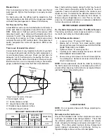
To confirm charge levels or, if a leak occurs and charge
needs to be added to the system, it is recommended to
evacuate the system and recharge refrigerant to the unit’s
nameplate specifications. This unit has been rated in the
cooling mode at the AHRI rated conditions of: indoor (80°F
db/67°F wb) and outdoor (95°F db). While operating at this
condition, units with a piston type metering device should
operate with a superheat range from 9° F to 11° F for each
refrigeration circuit measured at the suction service port lo-
cated near the compressor. For units with a TXV metering
device, the unit should operate within a subcooling range
of 14° to 16° for each refrigeration circuit measured at the
liquid line service port.
s
tart
-u
P
P
rOCedure
and
C
heCklist
Begin with power turned off at all disconnects.
a
ir
C
OnditiOning
s
tart
-u
P
P
rOCedure
1. Turn thermostat system switch to “Cool,” and fan switch
to “Auto” and turn temperature setting as high as it will
go.
2. Inspect all registers and set them to the normal open
position.
3. Turn on the electrical supply at the disconnect.
4. Turn the fan switch to the “ON” position. The blower
should operate after a 7 second delay.
5. Turn the fan switch to “Auto” position. The blower should
stop after a 65 second delay.
6. Slowly lower the cooling temperature until the unit starts.
The compressor, blower and fan should now be operat-
ing. Allow the unit to run 10 minutes, make sure cool air
is being supplied by the unit. On 2 stage models, (mod-
els with a “V” in the 11th position) the unit is now operat-
ing on low speed. After the 10 minute run, continue low-
ering cooling temperature until blower speed increases
indicating 2nd stage cooling. Make sure cool air is still
being supplied by unit and proceed to step 7.
7. Turn the temperature setting to the highest position,
stopping the unit. The indoor blower will continue to run
for 65 seconds.
8. Turn the thermostat system switch to “OFF” and discon-
nect all power when servicing the unit.
h
eat
P
umP
s
tart
-u
P
P
rOCedure
9. Check the cooling mode for the heat pump in the
same manner as above. The reversing valve is ener-
gized when the thermostat is placed in the cooling po-
sition. A clicking sound should be noticeable from the
reversing valve. By lowering the temperature setting
to call for cooling, the contractor is energized. The
compressor, blower and fan should then be running.
HIGH VOLTAGE!
D
ISCONNECT
ALL
POWER
BEFORE
SERVICING
OR
INSTALLING
THIS
UNIT
. M
ULTIPLE
POWER
SOURCES
MAY
BE
PRESENT
. F
AILURE
TO
DO
SO
MAY
CAUSE
PROPERTY
DAMAGE
,
PERSONAL
INJURY
OR
DEATH
.
WARNING
After the cooling mode is checked out, turn the thermo-
stat system switch to “OFF”.
10. Turn the thermostat system switch to “HEAT” and fan
switch to “AUTO”.
11. Slowly raise the heating temperature setting. When the
heating first stage makes contact, stop raising the tem
-
perature setting.. The compressor, blower and fan should
now be running with the reversing valve in the de-ener-
gized (heating) position. After giving the unit time to settle
out, make sure the unit is supplying heated air.
12. If the outdoor ambient is above 80°F, the unit may trip on
its high pressure cut out when on heating. The compres-
sor should stop. The heating cycle must be thoroughly
checked, so postpone the test to another day when con-
ditions are more suitable but-DO NOT FAIL TO TEST.
If the outdoor ambient is low and the unit operates prop-
erly on the heating cycle, you may check the pressure
cutout operation by blocking off the indoor return air until
the unit trips.
13. If unit operates properly in the heating cycle, raise the
temperature setting until the heating second stage makes
contact. Supplemental resistance heat, if installed should
now come on. Make sure it operates properly.
NOTE:
If outdoor thermostats are installed the outdoor
ambient must be below the set point of these thermostats
for the heaters to operate. It may be necessary to jumper
these thermostats to check heater operation if outdoor
ambient is mild.
14. For thermostats with emergency heat switch, return to
step 11. The emergency heat switch is located at the
bottom of the thermostat. Move the switch to emergency
heat. The heat pump will stop, the blower will continue to
run, all heaters will come on and the thermostat emer-
gency heat light will come on.
15. If checking the unit in the wintertime, when the outdoor
coil is cold enough to actuate the defrost control, observe
at least one defrost cycle to make sure the unit defrosts
completely.
f
inal
s
ystem
C
heCks
16. Check to see if all supply and return air grilles are adjust-
ed and the air distribution system is balanced for the best
compromise between heating and cooling.
17. Check for air leaks in the ductwork. See Sections on
Air
Flow Adjustments.
18. Make sure the unit is free of “rattles”, and the tubing in
the unit is free from excessive vibration. Also make sure
tubes or lines are not rubbing against each other or sheet
metal surfaces or edges. If so, correct the trouble.
19. Set the thermostat at the appropriate setting for cooling
and heating or automatic changeover for normal use.
20. Be sure the Owner is instructed on the unit operation,
filter, servicing, correct thermostat operation, etc.
r
efrigeratiOn
P
erfOrmanCe
C
heCk
Check that compressor RLA corresponds to values shown
in Appendix B. RLA draw can be much lower than values
Содержание DCC Series
Страница 45: ...45 THIS PAGE INTENTIONALLY LEFT BLANK ...
Страница 46: ...46 THIS PAGE INTENTIONALLY LEFT BLANK ...
Страница 47: ...47 THIS PAGE INTENTIONALLY LEFT BLANK ...


