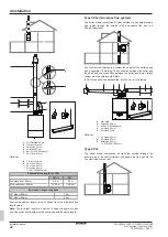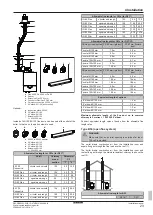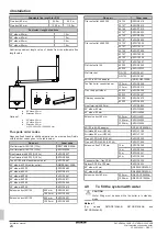
4 Installation
Installation manual
15
D2CND024A1/4AB + D2TND012~024A4AB
Wall-mounted condensing boiler
3P469346-3N – 2019.11
Temperature control units
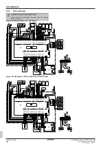
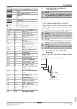
Connector
Connectio
n
Domestic hot water storage tank
sensor
X1M
7-8
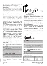
External power output (230 V AC)
X2M
3-4
On-Off room thermostat*
X2M
5-6
* On-Off room thermostat must have volt-free dry contact (230 V AC)
X1M
(1-2)
(3-4)
(5-6)
(7-8)
8
1
X2M
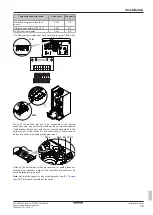
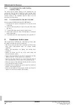
Wiring of the options that are to be connected to the internal
connectors must pop out from the inside of the unit via cable glands.
Cable glands that are sent with the unit must be assembled to the
bottom sheet of the boiler in case connection of these options.
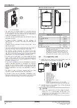
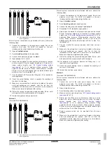
Below, you can see the cable glands placement.
PG 9
PG 9 PG 7 PG 7
Holes on the bottom sheet that are reserved for cable glands are
covered with insulation material. The insulation material must be
bored if glands are to be used.
Note:
Unit must be opened to mount cable glands. See
Содержание D2CND024A4AB
Страница 31: ......


