6
IOM 1206-1
Installation and Application Information
POE Lubricants
Chilled Water Piping
IMPORTANT:
Piping design must be provided by a qualified
Architect or Systems HVAC Design Engineer familiar with
piping design, as well as local codes and regulations. The
manufacturer recommendations provided here are to be used
as a general guide, but do not replace system design by a
qualified professional.
Install a cleanable perforated basket strainer with 0.062-inch
perforations and 40% open area for models 030 to 070 in the
water line just prior to the inlet of the evaporator. An optional
strainer kit is available for factory installation or field
mounting.
Design the water piping so the chilled water circulating pump
discharges into the evaporator inlet. Connect the return water
line to the evaporator inlet connection. Connect the supply
water line to the evaporator outlet connection. If not already
factory installed, install a flow switch in the horizontal piping
of the supply (evaporator outlet) water line.
Provide drain connections at low points in the system to permit
complete drainage of the system. Locate air vents at the high
points in the system to purge air out of the system. A vent
connection on top of the evaporator vessel allows air to be
purged out of the evaporator. Purge air from the water system
before unit start-up to provide adequate flow through the
evaporator.
Units with brazed-plate evaporators (030-070) must have a
drain connection provided in the bottom of the lower
connection pipe and a vent on the top of the upper connection
pipe. These evaporators do not have drain or vent connections
due to their construction.
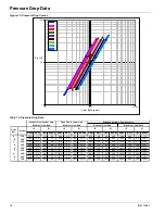
Install pressure gauges in the inlet and outlet water lines to the
evaporator. Measure pressure drop through the evaporator and
compare to flow as shown on
page 18
. Vibration eliminators
are recommended in both the supply and return water lines.
Insulate chilled water piping to reduce heat loss and prevent
condensation. Chillers not running in the winter should have
their water systems thoroughly drained to protect against
freezing. If the chiller operates year-round, or if the system is
not drained for the winter, protect the chilled water piping
exposed to outdoor temperature against freezing. Wrap the
lines with a heater cable and add proper amount of glycol to
the system to further protect the system.
Optional Inlet Strainer
An inlet water strainer kit is available to be field-installed,
sized per
Table 2
and with the pressure drop show in
Figure 6
.
This pressure drop must be accounted for in the total system
pressure drop. The kit consists of:
• (1) Y-type 40% open area strainer with 304 stainless
steel perforated basket, Victaulic pipe connections and
strainer cap.
• (1) Extension pipe with (2) Schrader fittings that can be
used for a pressure gauge and thermal dispersion flow
switch. The pipe provides sufficient clearance from the
evaporator for strainer basket removal.
• (1) ½-inch blowdown valve.
• (2) Victaulic clamps.
Figure 6: Strainer Pressure Drop
Table 2: Strainer Data
WARNING
Thus unit contains POE lubricants that must be handled carefully and the proper protective equipment (gloves, eye
protection, etc.) must be used when handling POE lubricant. POE must not come into contact with any surface or
material that might be harmed by POE, including certain polymers (e.g. PVC/CPVC and polycarbonate piping)
.
!
AGZ Model
Strainer Size
(in.)
Strainer Plus Pipe
Length (in.)
Strainer
Weight (lbs)
030-055
2.5
16.75
14
060-070
3.0
17.75
20


