IOM 1206-1
25
Unit Controller Operation
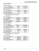
Compressor Module 1
Table 25: Analog Inputs
Table 26: Digital Inputs
Note:
The Motor Protection and MHP input signal are wired in
series. If Motor Protection input is open, MHP Switch
input will also be open.
Table 27: Digital Outputs
Compressor Module 2
Table 28: Analog Inputs
Table 29: Digital Inputs
Note:
The Motor Protection and MHP input signal are wired in
series. If Motor Protection input is open, MHP Switch
input will also be open.
Table 30: Digital Outputs
Description
Signal Type
Expected Range
X1
Circuit 1 Suction Temperature
NTC 10k
340 to 300k
Ω
X2
Circuit 1 Evaporator Pressure
Voltage
0.4 to 4.6 volts
X4
Circuit 1 Condenser Pressure
Voltage
0.4 to 4.6 volts
Description
Signal Off
Signal On
X6
Circuit 1 Switch
Circuit Disable
Circuit Enable
X7
Circuit 1 MHP Switch
Fault
No fault
X8
Circuit 1 Motor Protection
Fault
No fault
DI1
Circuit 1 (or Unit) PVM/GFP
Fault
No fault
Description
Output Off
Output On
DO1
Compressor #1
Compressor Off
Compressor On
DO2
Compressor #3
Compressor Off
Compressor On
DO3
Compressor #5
Compressor Off
Compressor On
DO4
Evaporator Water Pump 2
Pump Off
Pump On
DO5
Circuit 1 Hot Gas Bypass SV
Solenoid Closed
Solenoid Open
DO6
Circuit 1 Liquid Line SV
Solenoid Closed
Solenoid Open
Description
Signal Type
Expected Range
X1
Circuit 2 Suction Temperature
NTC 10k
340 to 300k
Ω
X2
Circuit 2 Evaporator Pressure
Voltage
0.4 to 4.6 volts
X4
Circuit 2 Condenser Pressure
Voltage
0.4 to 4.6 volts
Description
Signal Off
Signal On
X6
Circuit 2 Switch
Circuit Disable
Circuit Enable
X7
Circuit 2 MHP Switch
Fault
No fault
X8
Circuit 2 Motor Protection
Fault
No fault
DI1
Circuit 2 PVM/GFP
Fault
No fault
Description
Output Off
Output On
DO1
Compressor #2
Compressor Off
Compressor On
DO2
Compressor #4
Compressor Off
Compressor On
DO3
Compressor #6
Compressor Off
Compressor On
DO5
Circuit 2 Hot Gas Bypass SV
Solenoid Closed
Solenoid Open
DO6
Circuit 2 Liquid Line SV
Solenoid Closed
Solenoid Open


