3.3 Editing Using an External Personal Computer
3-15
Sample of format
Explanation
[CNT_TOUCHPANEL]
ENABLED=0
AUTODISP=1
COMMON_SW=1
CSW_DIRECTION=0
CSW_EKEY=0
[IN_ASSIGN]
IN_TouchStrb=0
IN_TouchPageBit=0,0,0,0
[CNT_TOUCHPANEL] must be described without fail.
Following "ENABLED=," the "Interface Panel" setting is described.
0: Use; 1: Not Use
Following AUTODISP=, the "AutoDisp" setting is described.
0: Enabled; 1: Disabled
Following COMMON_SW=, the "Common Switch" setting is described.
0: Previous No.; 1: Disabled
CSW_DIRECTION=, the "Common Switch ON Direction" setting is
described.
0; Left
、
1; Right
CSW_EKEY=, the "Common Switch Operation Method" setting is
described.
0; Standard
、
1; Enable
[IN_ASSIGN] must be described without fail.
Following IN_TouchStrb=, the "Strobe input signal number" setting is
described.
Following IN_TouchPageBit=, four "Page selection input signal numbers"
are described using commas as delimiters.
Fig. 3.3.3 Format for condition settings
Operation switches
Following the [TOUCHINI] key name, the parameters for the operation switches are listed.
Even if an operation switch is not going to be used, it must be described without fail.
Sample of format
Explanation
[TOUCHINI]
P1_1A=3000
P1_1A_NAME=" Auto"
P1_1A_DATA=15, 15, 0, 0,
0, 2, 0, 0, 0, 0, 0, 0, 0, 0, 0,
0, 0, 0, 0, 0, 0, 0, 0, 0, 0, 0,
0, 0, 0, 0
[TOUCHINI] must be described without fail (at the top only).
Following "the page number_position number=," the "Operation switch
code numbers" are described. Refer to Table 3.2.2 List of operation
switch keys for the code numbers.
Following "the page number_position number_NAME=," the "operation
switch display names (standard)" are described inside double quotation
marks.
Following "the page number_position number_DATA=," the "operation switch
detailed data" is described using a succession of numbers and commas.
The number of parameters varies with the types of operation switches.
If there are not many parameters described, an error will occur when a file
import is executed, executing no file conversions.
For details, refer to information in Table 3.3.1 Format for detailed data of
operation switches.
Fig. 3.3.4 Format for operation switches
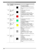
Refer to the table below for the format which is used for the detailed data of the operation switches (the group of
parameters following P*_**_DATA=).
Table 3.3.1 Format for detailed data of operation switches
Description of
function
External appearance
Format
Code
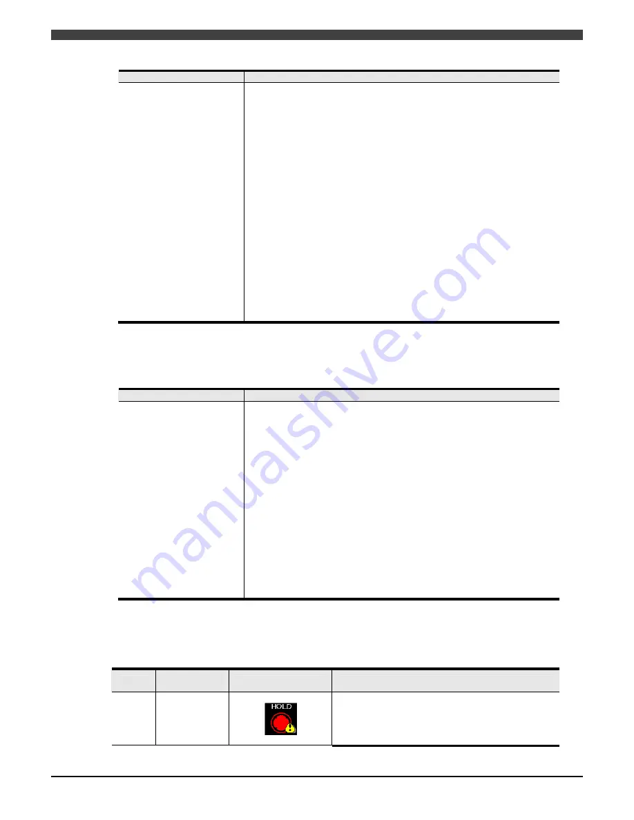
3000 Round
lamp
In sequence from the first parameter:
1: Color when ON
2: Color when OFF
3: Display data selection (0: Input signal/1: Output signal)

