background image

3.3 Editing Using an External Personal Computer 

3-15 


Sample of format 

Explanation 

 
[CNT_TOUCHPANEL] 
 
ENABLED=0 
 
AUTODISP=1 
 
COMMON_SW=1 
 
CSW_DIRECTION=0 
 
CSW_EKEY=0  
 
[IN_ASSIGN] 
 
IN_TouchStrb=0 
 
 
IN_TouchPageBit=0,0,0,0 


[CNT_TOUCHPANEL] must be described without fail. 
 
Following "ENABLED=," the "Interface Panel" setting is described. 

0: Use; 1: Not Use 

Following AUTODISP=, the "AutoDisp" setting is described. 

0: Enabled; 1: Disabled 

Following COMMON_SW=, the "Common Switch" setting is described. 

0: Previous No.; 1: Disabled 

CSW_DIRECTION=, the "Common Switch ON Direction" setting is 
described. 

0; Left

1; Right 

CSW_EKEY=, the "Common Switch Operation Method" setting is 
described. 

0; Standard

1; Enable 

[IN_ASSIGN] must be described without fail. 
 
Following IN_TouchStrb=, the "Strobe input signal number" setting is 
described. 
 
Following IN_TouchPageBit=, four "Page selection input signal numbers" 
are described using commas as delimiters. 
 

Fig. 3.3.3    Format for condition settings 


 Operation switches 
Following the [TOUCHINI] key name, the parameters for the operation switches are listed. 
Even if an operation switch is not going to be used, it must be described without fail. 


Sample of format 

Explanation 

 
[TOUCHINI] 
 
P1_1A=3000 


P1_1A_NAME=" Auto" 


P1_1A_DATA=15, 15, 0, 0, 
0, 2, 0, 0, 0, 0, 0, 0, 0, 0, 0, 
0, 0, 0, 0, 0, 0, 0, 0, 0, 0, 0, 
0, 0, 0, 0 


[TOUCHINI] must be described without fail (at the top only). 
 
Following "the page number_position number=," the "Operation switch 
code numbers" are described. Refer to Table 3.2.2  List of operation 
switch keys
 for the code numbers. 
 
Following "the page number_position number_NAME=," the "operation 
switch display names (standard)" are described inside double quotation 
marks. 
 
Following "the page number_position number_DATA=," the "operation switch 
detailed data" is described using a succession of numbers and commas. 
The number of parameters varies with the types of operation switches. 
If there are not many parameters described, an error will occur when a file 
import is executed, executing no file conversions. 
For details, refer to information in Table 3.3.1    Format for detailed data of 
operation switches


Fig. 3.3.4    Format for operation switches 


Refer to the table below for the format which is used for the detailed data of the operation switches (the group of 
parameters following P*_**_DATA=). 


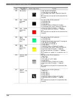
Table 3.3.1    Format for detailed data of operation switches 

Description of 

function 

External appearance

Format 

Code 

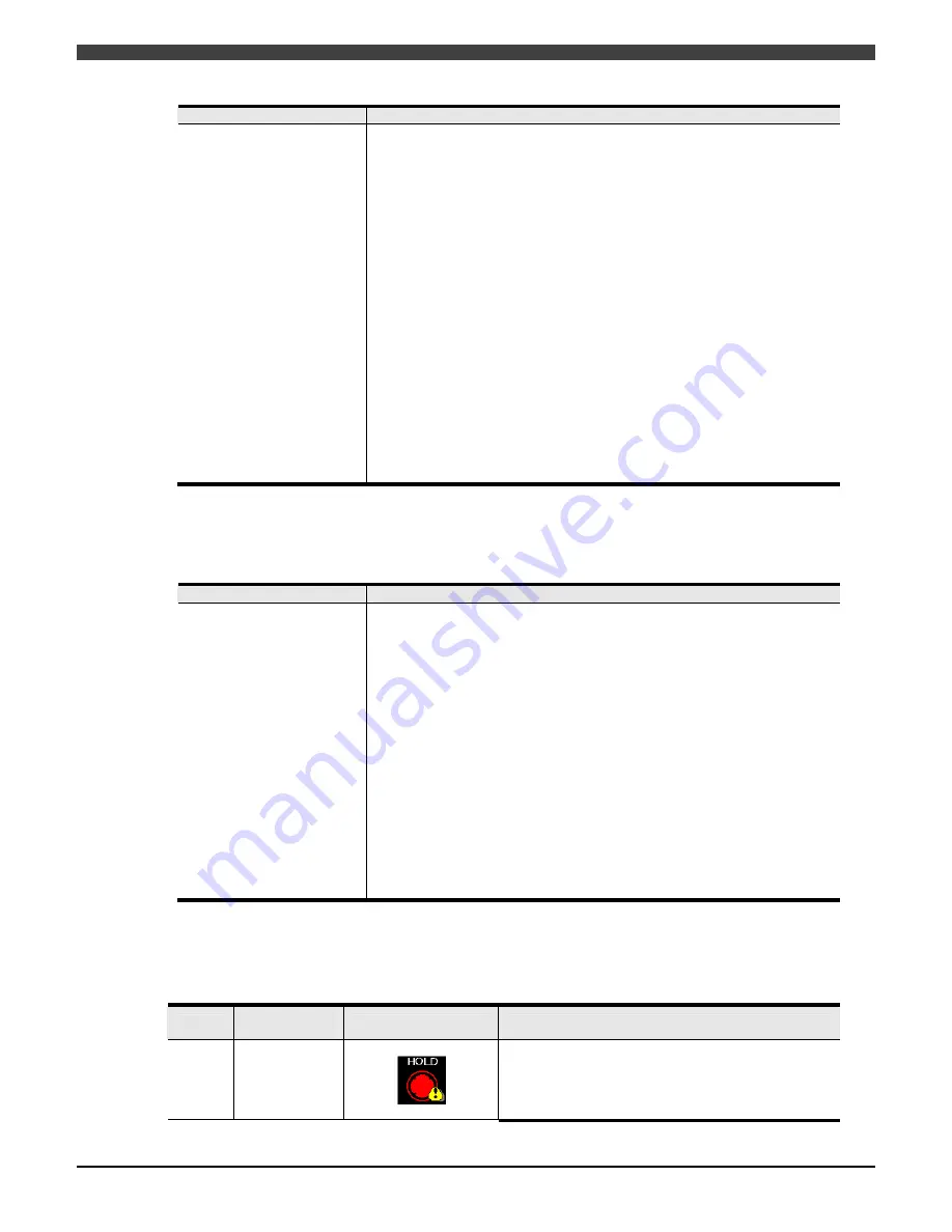
3000 Round 

lamp 


In sequence from the first parameter: 
1: Color when ON 
2: Color when OFF 
3: Display data selection (0: Input signal/1: Output signal)

Содержание OTC ALMEGA FD Series

Страница 1: ...N MANUAL INTERFACE PANEL Read and follow these instructions and all safety blocks carefully Have only trained and qualified persons install operate or service this unit Give this manual to the operato...

Страница 2: ......

Страница 3: ...lanation of manual operation teaching automatic operation file utilities backing up data basic operations of Arc Spot welding application etc EXTERNAL INPUT OUTPUT 1L21700H Interfacing method with ext...

Страница 4: ...high level danger 2 WARNING Cases where a mistake made in handling is likely to cause the user to be exposed to the danger of death or serious injury CAUTION Cases where a mistake made in handling is...

Страница 5: ...ontrolling the common switch using an input signal 2 5 2 1 8 Checking the status of the common switch 2 6 2 1 9 Setting of softkey output signal for general purpose usage 2 6 Chapter 3 Screen Design 3...

Страница 6: ...Table of Contents 2 4 1 Basic Operation 4 1 4 1 1 Opening the interface panel and changing the pages 4 1 4 1 2 Using operation switches 4 3...

Страница 7: ...ons lamps etc to be displayed on the touch panel of the teach pendant 1 1 General Description of Interface Panel Function 1 1 1 1 1 General description 1 1 1 1 2 Specification 1 1 1 1 3 Signal attribu...

Страница 8: ......

Страница 9: ...Table 1 1 1 Specifications of interface panel function Since a total of 248 switches can be designed exactly as desired on up to 8 screens screens can be designed flexibly to suit the applications Ta...

Страница 10: ...l control variables Interface panel outputs Push buttons selector switches etc Interface panel inputs Lamps displays etc Start instruction servo ON instruction and other status output signals General...

Страница 11: ...divided into two constants files the controller general constants file and I O constants file and stores the files in the memory This is because the information does not only involve the screen displ...

Страница 12: ...g on the operation method Define the method to be used to open the interface panel screen the default values of the common switches and other contents 1 2 3 Operation Open the interface panel screen a...

Страница 13: ...3 Setting of the initial status of the common switch 2 2 2 1 4 Setting of Enable Disable of functionless code switch name setting 2 3 2 1 5 Setting of signal duplication check 2 4 2 1 6 Setting of En...

Страница 14: ......

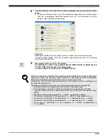
Страница 15: ...such as the one shown below appears 2 Select 1 Touch Panel Conditions A setting screen such as the one shown below appears Align the cursor with Interface Panel and select the Use setting using the EN...

Страница 16: ...terpreted as a binary data The signal 1 is the lowest and the signal 4 is the highest If all bits are set to off the page number is set to 0 that is to say the interface panel screen is closed The tim...

Страница 17: ...out pressing the ENABLE key Enable No operations are enabled unless the ENABLE key is pressed 3 4 Upon completion of settings mentioned above press the f12 Complete key 2 1 4 Setting of Enable Disable...

Страница 18: ...setting Upon completion of settings mentioned above press the f12 Complete key 2 2 1 6 Setting of Enable Disable of operations of f keys on touch panel Make setting of whether the operations of soft...

Страница 19: ...nds on the signal status at the timing of the power ON Operation of the common switch Because the common switch is controlled by the input signal the operation for this switch on the touch panel is ig...

Страница 20: ...ternation type 3010 Selector switch ON OFF 3003 Push Button momentary type 3030 Input 3digits 3004 Flash Push Button alternation type 3030 Input 6digits only for interface panel 3005 Flash Push Button...

Страница 21: ...ht hand corner 3 1 3 2 Operation Switch Design 3 2 3 2 1 Basic operations for operation switch design 3 2 3 2 2 Round lamps and square lamps 3 7 3 2 3 Push buttons 3 8 3 2 4 Flash push buttons 3 9 3 2...

Страница 22: ......

Страница 23: ...This is the selector switch that enables or disables interface panel operations This switch functions when it is pressed together with the ENABLE key or individually by itself according to the settin...

Страница 24: ...the settings All the keys are set to No Function at the default setting At the far left the layout numbers of the keys are indicated as a combination of the page number and position number and to the...

Страница 25: ...itch f keys on both sides of mode screen Lamps push buttons etc Select the desired item from the code list using the Up or Down cursor key and press the Enter key to insert the code Alternatively the...

Страница 26: ...tSignal and input the number of the signal As a general rule logical input signals are allocated as the lamp display and other interface panel inputs and logical output signals are allocated to the pu...

Страница 27: ...disables the operations It cannot be deleted or changed 13 Upon completion of the settings press f12 Complete The settings are saved in the constants files S SIGL CON I O constants file and C CTRL CO...

Страница 28: ...tuses of the input signals or output signals 3010 Selector switch ON OFF Output signal ON OFF selector switch These buttons turn the output signals ON or OFF when operated by the operator 3011 Contact...

Страница 29: ...itial value 3000 Round lamp Top comes on Bottom goes off ON OFF display lamp Color of OFF Color of ON Display data Input signal output signal Input Signal 1bit 0 2048 Output Signal 1bit 0 2048 mark do...

Страница 30: ...d Push button switch operation holding type Color of ON Color of OFF Output Signal 1bit 0 2048 Operation method Standard Enable mark don t show when ON when OFF Operation inhibit Enabled Disabled Touc...

Страница 31: ...r of ON Color of OFF Display data Input signal output signal Input Signals 1bit 0 to 2048 Output Signals 1bit 0 to 2048 Output Signal Operation method Standard Enable mark don t show when ON when OFF...

Страница 32: ...tion inhibit Enabled Disabled Black White Right 0 Standard Enabled 3 2 6 Selector switches 2 contact type Details setting screen Code Description of function External appearance Outline Parameter Init...

Страница 33: ...utput Signal Variable Int Method of read Data format Binary BCD Input Signal 0 to 2048 12bit 1 LSB 12 MSB Output Signal 0 to 2048 12bit 1 LSB 12 MSB Variable integer Global variable only 0 to 200 Whit...

Страница 34: ...output signals Input range 0 to 999 Base color Method of Output Binary BCD Output Signal 0 to 2048 12bit 1 LSB 12 MSB Operation inhibit Enabled Disabled White Binary All 0 Enabled Left side 3031 Right...

Страница 35: ...commercially available Direct editing Interface panel files Displa Fig 3 3 1 Designing screens using an external personal computer 3 3 2 Editing using a personal computer When using a personal comput...

Страница 36: ...ample of interface panel file Prepare interface panel files in the INI file format under the filenames of AC IFP CON where denotes a 2 digit integer and load them into the robot controller using a Com...

Страница 37: ...on TOUCHINI P1_1A 3000 P1_1A_NAME Auto P1_1A_DATA 15 15 0 0 0 2 0 0 0 0 0 0 0 0 0 0 0 0 0 0 0 0 0 0 0 0 0 0 0 0 TOUCHINI must be described without fail at the top only Following the page number_positi...

Страница 38: ...he first parameter 1 Color when ON 2 Color when OFF 3 Display data selection 0 Input signal 1 Output signal 4 Input signal to be displayed 5 Output signal to be displayed 6 Output signal 7 Operation m...

Страница 39: ...layed 1 27 Input signal to be displayed 24 28 0 No descriptions are required for all parameters from 29 onward 13021 display 6 digits right side In sequence from the first parameter 1 Output signal to...

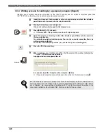
Страница 40: ...other storage device and install it in the robot controller 2 Display the interface panel design list It does not matter which page the list display is on 3 Press f10 import The file operation screen...

Страница 41: ...ion source file has any erroneous description keywords on lines with erroneous display contents of import results will be all displayed Referring to this display make corrections to the conversion sou...

Страница 42: ...as the copy destination To overwrite an existing interface panel file use the cursor to select the file to be written and press Enter To create a new interface panel file do not select any of the exi...

Страница 43: ...tilization of the Interface Panel This chapter describes how to utilize the interface panel 4 1 Basic Operation 4 1 4 1 1 Opening the interface panel and changing the pages 4 1 4 1 2 Using operation s...

Страница 44: ......

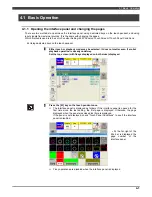
Страница 45: ...selected It does not matter even if a robot playback operation is already underway Set the top screen with f keys displayed on both sides displayed Press the I F key on the teach pendant once The inte...

Страница 46: ...NT Bear in mind that pressing ENABLE and Up or Down cursor keys when the interface panel is not open can change the current step 4 Press the I F key on the teach pendant once again The top screen of t...

Страница 47: ...h button Pressing this key switches the status between ON OFF in the alternation or momentary mode Operation with ENABLE also available Selector switch Pressing this key switches the position between...

Страница 48: ...4 1 Basic Operation 4 4 NOTE...

Отзывы: