


3.2 Operation Switch Design
3-4
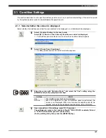
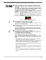
On this screen, set the color, input/output signals and other detail data.
In the example presented above, the setting screen for a round lamp is shown. The
contents of the setting screen will differ depending on the type of operation switch
concerned.
Align the cursor with "Color", and press the [Enter] key.
Sixteen color options are displayed. Select the desired color using the [Up] or
[Down] cursor key, and then press the [Enter] key.
In the case of a round lamp, for example, select one color to indicate ON and
another color to indicate OFF.
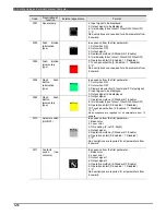
Table 3.2.1 List of colors
Color no.
Color name
Color no.
Color name
0 Black 8
Medium
gray
1 Dark
red 9
Red
2
Dark green
10
Green
3 Dark
yellow
11
Yellow
4 Dark
blue
12
Blue
5 Dark
magenta
13
Magenta
6 Dark
cyan
14
Cyan
7 Light
gray
15
White
8
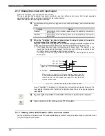
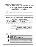
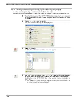
Next, set the input and output signals.
Align the cursor with "InputSignal" or "OutputSignal", and input the number of
the signal.
As a general rule, logical input signals are allocated as the lamp, display and
other interface panel inputs and logical output signals are allocated to the push
buttons, selector switches and other interface panel outputs.
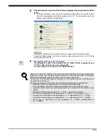
However, as explained in
"Chapter 1 General description", either logical input
signals or logical output signals can be used for the interface panel inputs, and in
addition, internal control variables can be applied to some of the interface panel
inputs.
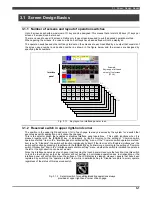
With the interface panel inputs, first specify the input sources using "Display
data", and then set the numbers of the logical input (or output) signals.
9
Number
Display data selection
Internal control
variables
Individually set
Interface panel outputs
Push buttons, selector switches, etc.
Interface panel inputs
Lamps, displays, etc.
2048
logical
input
signals
2048
logical
output
signals
Outside
Fig. 3.2.1 Overview of input/output signals used by interface panel
When "0" is set as the signal number, no input/output operations are executed. (Only
the operation switch display appears.)


