239
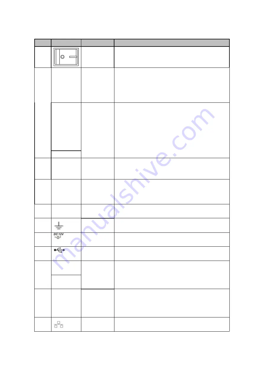
Please refer to the following sheet for detailed information.
SN
Icon
Name
Note
1
Power switch Power on/off button.
2
1
~
8(16)
Alarm input
port 1
~
8(16)
There are two types; NO (normal open)/NC
(normal close).
When your alarm input device is using external
power, please make sure the device and the DVR
have the same ground.
NO1
~
NO3
Alarm output
port 1
~
3
3 groups of alarm output ports. (Group 1:port
NO1
~
C1,Group 2:port NO2
~
C2,Group 3:port
NO3
~
C3
)
).Output alarm signal to the alarm
device. Please make sure there is power to the
external alarm device.
NO:Normal open alarm output port.
C:Alarm output public end.
C1
~
C3
3
VGA
VGA
video
output
port
VGA video output port. Output analog video signal.
Can connect to the monitor to view ananlog video
output.
4
AUDIO IN
Audio
input
port
Connect to audio input device such as speaker.
5
VIDEO IN
Video
input
port
Connect to analog camera, video input signal.
6
GND
Alarm input ground port.
7
Power input
port
Input 12V DC.
8
USB2.0 port
Connect to USB storage device, mouse, burning
DVD-ROM and etc.
9
A
RS485
(
RS-485
)
communicati
on port
RS485_A port. It is the cable A. You can connect to
the control devices such as speed dome PTZ.
B
RS485_B.It is the cable B. You can connect to the
control devices such as speed dome PTZ.
10
HDMI
High
Definition
Media
Interface
High definition audio and video signal output port. It
transmits uncompressed high definition video and
multiple-channel data to the HDMI port of the display
device.
11
Network port
100M Ethernet port
Содержание HCVR2104HS-S3
Страница 1: ...Dahua HDCVI Standalone DVR User s Manual Dahua HDCVI Standalone DVR User s Manual V2 3 2 ...
Страница 200: ...184 ...
Страница 402: ...386 restore original status Figure 4 115 Figure 4 116 4 9 1 3 1Upgrade Camera It is to update the online camera ...
Страница 425: ...409 Figure 4 137 Figure 4 138 ...
Страница 432: ...416 Figure 4 145 Step 2 Draw tripwire 1 Click Draw button to draw the tripwire See Figure 4 146 Figure 4 146 ...
Страница 436: ...420 Figure 4 149 Step 2 Draw the zone 1 Click draw button to draw the zone See Figure 4 150 Figure 4 150 ...
Страница 438: ...422 Figure 4 151 Step 2 Draw the zone 1 Click draw button to draw the zone See Figure 4 152 Figure 4 152 ...
Страница 440: ...424 Figure 4 153 Step 2 Draw the zone 1 Click Draw button to draw a zone See Figure 4 154 ...
Страница 446: ...430 Figure 4 157 Figure 4 158 ...
Страница 447: ...431 Figure 4 159 Figure 4 160 ...
Страница 448: ...432 Figure 4 161 Figure 4 162 ...
Страница 451: ...435 Figure 4 165 Figure 4 166 ...
Страница 452: ...436 Figure 4 167 Figure 4 168 ...
Страница 458: ...442 Figure 4 177 Figure 4 178 4 9 4 1 2 2 Trigger Snapshot ...
Страница 460: ...444 Figure 4 180 Figure 4 181 4 9 4 1 2 3 Priority ...
Страница 466: ...450 Figure 4 186 Figure 4 187 ...
Страница 471: ...455 Figure 4 193 Figure 4 194 ...
Страница 484: ...468 Figure 4 209 For digital channel the interface is shown as below See Figure 4 210 Figure 4 210 ...
Страница 491: ...475 Figure 4 218 Step 2 Click Add user button in Figure 4 218 The interface is shown as in Figure 4 219 Figure 4 219 ...
Страница 557: ...541 Figure 5 69 Figure 5 70 ...
Страница 573: ...557 device Figure 5 86 Figure 5 87 ...
Страница 579: ...563 Figure 5 94 Figure 5 95 ...
Страница 580: ...564 Figure 5 96 Figure 5 97 Please refer to the following sheet for detailed information ...
Страница 584: ...568 Figure 5 101 Figure 5 102 Figure 5 103 Please refer to the following sheet for detailed information ...
Страница 607: ...591 Figure 5 136 Note For admin you can change the email information See Figure 5 137 ...
Страница 637: ...621 448K 196M 512K 225M 640K 281M 768K 337M 896K 393M 1024K 450M 1280K 562M 1536K 675M 1792K 787M 2048K 900M ...